Power / Portable Power Stations
Assembly Instructions for Global Industrial 1-Tier Wood Locker
Comprehensive assembly and installation guide for the Global Industrial 1-Tier Wood Locker. Includes hardware lists, wall mounting procedures, hinge adjustments, and optional lock installation steps.
Table of contents
Manual images
Click an image to enlargeImportant Information
The Global Industrial 1-Tier Wood Locker supports a maximum weight of 18kg. For maintenance, clean the surface using a piece of flannel dampened with a water and alcohol solution. Avoid direct sunlight to prevent damage to the finish.
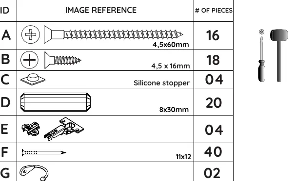
Hardware List
Before beginning assembly, verify all hardware components are present. The hardware drawings in the manual are full-scale for easy identification. Ensure you have all items from A to Q before starting.
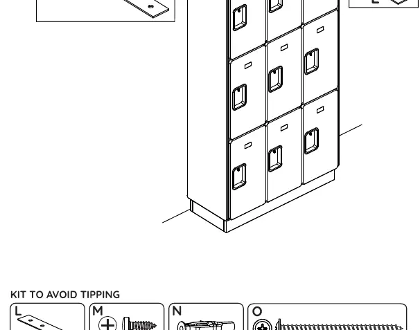
Wall Mounting and Safety
To prevent tipping, cabinets must be secured to the wall. Ensure the installation area is plumb and level. Use the provided kit (L, M, N, O) to secure the cabinets to the wall. For back-to-back installations, ensure side panels touch each other and secure the metal plates on top of the cabinets.
Assembly Steps
Follow these steps for assembly:
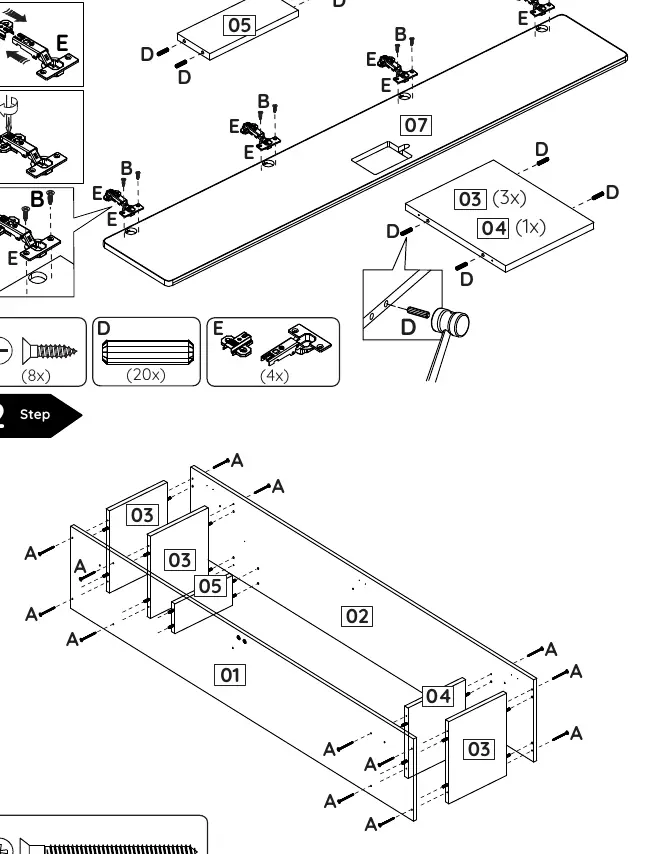
- Step 1: Install hinges (E) and hardware (B, D) onto the panels.
- Step 2: Assemble the cabinet body using screws (A).
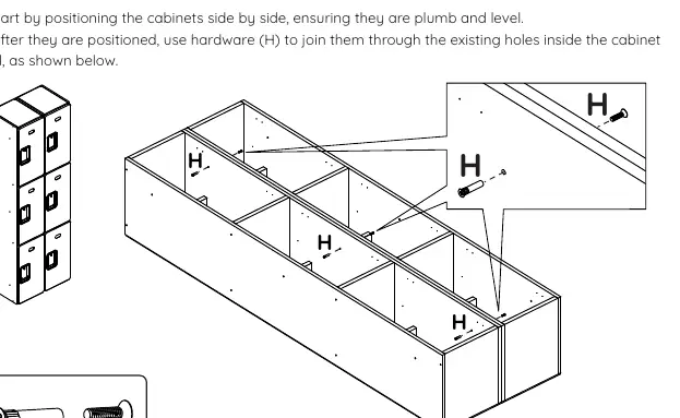
- Step 3: Join cabinets side-by-side using hardware (H).
- Step 4: Install accessories like hooks (G) if applicable.
- Step 5: Attach the name plate (K) and adjust door hinges.
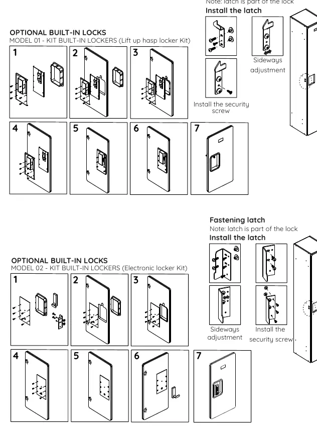
- Step 6: Install optional built-in locks (Model 01 or 02) if purchased.
Door Hinge Adjustment
The hinges allow for three-dimensional adjustment to ensure the door hangs correctly:
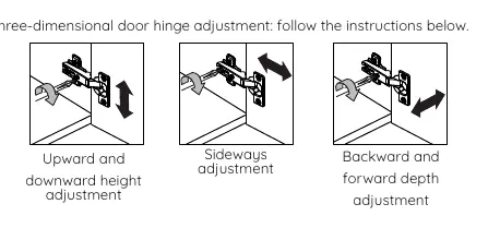
- Upward and downward height adjustment.
- Sideways adjustment.
- Backward and forward depth adjustment.
Practical help
Common problems
Cabinet tipping over
Ensure the cabinet is secured to the wall using the provided anti-tip kit (L, M, N, O).
Door misalignment
Use the three-dimensional hinge adjustment screws to align the door height, sideways position, and depth.
Surface damage
Avoid direct sunlight and clean only with a flannel cloth dampened with a water and alcohol solution.
Before use
- Ensure the installation area is plumb and level.
- Verify all hardware pieces (A-Q) are present according to the hardware list.
- Check that side panels are properly installed and touching the wall or adjacent cabinet.
- Confirm the maximum weight capacity of 18kg is not exceeded.
Specs in practice
- Maximum Weight Supported
- 18kg per locker unit.
- Hardware Scale
- Hardware drawings in the manual are full-scale (1:1) for easy identification.
Images and diagrams
- Hardware List: Identifies all screws, stoppers, and brackets required for assembly.
- Wall Mounting: Shows how to secure the cabinet to the wall to prevent tipping.
- Hinge Adjustment: Illustrates the three directions of adjustment for the door hinges.
- Lock Installation: Step-by-step guide for installing optional Model 01 or Model 02 locks.
Model compatibility
- Side panels and metal bases are add-on components sold separately.
- Optional built-in locks (Model 01 and Model 02) are available upon request.

Manual page author
Emily Carter
User documentation editor
Prepares concise manual descriptions and highlights the most useful setup, operation, and maintenance information for readers.