Baby / Baby Furniture
Installation Guide for HALO Heat & System 2-Zone Extension 222145
Comprehensive installation and setup guide for the HALO Heat & System 2-Zone Extension (222145). Includes location guidelines, mounting instructions, pairing procedures, and a commissioning checklist for professional installers.
Quick answers from the manual
Quick answer
- The HALO Heat & System 2-Zone Extension (222145) is a kit for adding a second heating zone to compatible Ideal boilers. It requires professional installation and pairing with the Smart Interface. p. 2
Key actions
- Install Halo PRT p. 6, 7
First start
- Insert batteries, follow on-screen pairing guide, select boiler type and zone, complete commissioning checklist. p. 8, 9, 10
Problems and fixes
Signal issues
Avoid metal/stone obstacles, use Zigbee Booster if >30m.
p. 4Technical specifications
| Parameter | Value | Meaning | Pages |
|---|---|---|---|
| RF Frequency | 2405 – 2480MHz Max. | Operating frequency range | p. 12 |
| RF Output Power | 10dBm | Maximum RF output power | p. 12 |
Where to find it in the PDF
- Kit Contents p. 3
- Location Guidelines p. 4
- System Overview p. 5
- Installing the Halo PRT p. 6, 7
- Commissioning Checklist p. 10, 11
Table of contents
Manual images
Click an image to enlargeQuick Guide from the Manual
The HALO Heat & System 2-Zone Extension (222145) is designed to add a second heating zone to compatible Ideal boilers. Important: This product must be installed by a competent person with appropriate safety qualifications. It is compatible with specific Ideal boiler models (Logic Heat/System, Vogue, etc.). Ensure the Smart Interface is in pairing mode (LED flashing red) before attempting to pair the Halo PRT.
Kit Contents
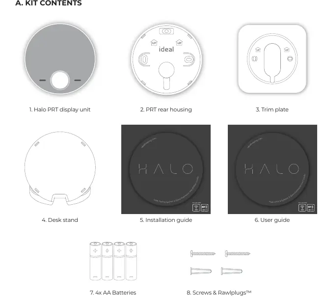
- Halo PRT display unit
- PRT rear housing
- Trim plate
- Desk stand
- Installation guide
- User guide
- 4x AA Batteries
- Screws & Rawlplugs
Location Guidelines
To ensure optimal Zigbee communication (up to 30 meters):
- Mount 1.2-1.5m above the floor.
- Do not mount above a radiator or heat source.
- Avoid direct sunlight and drafts.
- Do not fit behind curtains.
- Avoid directing communication through metal frames or solid concrete walls.
- For internal use only.
Installing the Halo PRT
Wall Mounting:
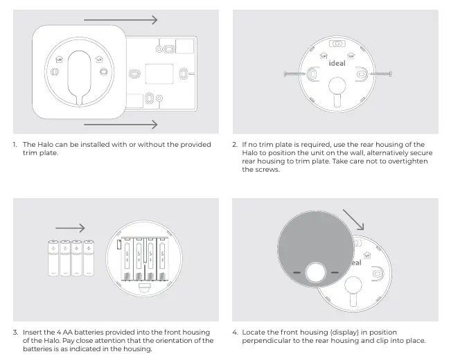
- Decide if the trim plate is required.
- Secure the rear housing to the wall (or trim plate), taking care not to overtighten screws.
- Insert 4x AA batteries into the front housing, observing correct orientation.
- Clip the front housing onto the rear housing.
Desk Mounting:
- Use the integrated rear housing and desk stand.
- Insert 4x AA batteries.
- Clip the combined rear housing and desk stand into place.
Pairing the Halo
Ensure the Smart Interface is in pairing mode (Zigbee LED flashing red).

- Insert batteries to power up the Halo PRT.
- Follow the on-screen guide to select the boiler type (Heat & System) and system type (Two zone heating and hot water).
- Select the appropriate zone (Zone 1 or Zone 2).
- Wait for "Pairing Complete" on the screen.
- Set up time and date.
Commissioning Checklist
Once set up, use the commissioning checklist to verify:
- Identify function: Confirm successful pairing (Zigbee LED flashes green on Smart Interface).
- RSSI Check: Verify signal strength (Target RSSI between 0 and -65, text green).
- Functional Test: Test heating and hot water modes (AUTO mode, check boiler firing and zone valve operation).
Practical help
Common problems
Poor signal strength or communication failure
Ensure communication path is not through stone or metallic objects. If distance > 30m, consider using the Zigbee Booster (UIN 221132).
Pairing fails
Ensure the Smart Interface is in pairing mode (Zigbee LED flashing red) before starting the process on the Halo PRT.
Before use
- Ensure installation is performed by a competent person with appropriate safety qualifications.
- Verify compatibility with your specific Ideal boiler model.
- Ensure the Smart Interface is installed and powered.
- Have 4x AA batteries ready for the Halo PRT.
- Check that the installation location is free from metal/stone obstructions.
Specs in practice
- RF Frequency
- 2405 – 2480MHz Max.
- RF Output Power
- 10dBm
- Communication Range
- Up to 30 meters (reduced by solid/metallic objects).
Images and diagrams
- System Overview: Illustrates communication paths between Halo units, Smart Wiring Centre, and Smart Interface.
- Location Guidelines: Shows optimal placement (1.2-1.5m height) and restricted areas (near heat sources, drafts, curtains).
Model compatibility
- Compatible with: Logic Heat H, Logic Heat H IE, Logic System S, Logic System S IE, Logic+ Heat H, Logic+ System S, Logic Max Heat H, Logic Max Heat H IE, Logic Max System S, Logic Max System S IE, Keston System, Vogue System, Vogue GEN2...

Manual page author
Emily Carter
User documentation editor
Prepares concise manual descriptions and highlights the most useful setup, operation, and maintenance information for readers.