HVAC / Thermostats & Controls
User Manual for MCO Home Z-Wave Thermostat (2-pipe)
Quick guide for the MCO Home Z-Wave Thermostat (2-pipe) (MCOEMH8-FC). Learn how to install, wire, include in a Z-Wave network, and configure settings.
Quick answers from the manual
Quick answer
- The MCOEMH8-FC is a Z-Wave enabled thermostat for 2-pipe fan coil systems. It requires professional installation for mains power, supports Z-Wave network inclusion/exclusion, and offers configurable parameters for temperature and fan control. p. 1, 2
Key actions
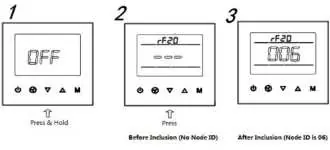
- Inclusion/Exclusion p. 2, 3
- Parameter Settings p. 4
First start
- Power on, press On/Off button to enter working interface. p. 2, 3
Problems and fixes
Inclusion fails
Ensure device is in factory reset state, check frequency, remove dead devices.
p. 4Maintenance and reset
- Factory restore via parameter P-10 (Write 55). p. 4
Technical specifications
| Parameter | Value | Meaning | Pages |
|---|---|---|---|
| Power Supply | AC85V~260V | Mains power | p. 4 |
| Load | 3A | Resistive load limit | p. 4 |
Where to find it in the PDF
- Quickstart and Safety p. 1
- Installation and Wiring p. 2
- Product Usage p. 3
- Parameters and Specs p. 4
Table of contents
Manual images
Click an image to enlargeQuick guide from the manual
The MCO Home Z-Wave Thermostat (2-pipe) is designed for indoor temperature control in 2-pipe fan coil systems. To begin, ensure the device is in factory default state before attempting to include it in a Z-Wave network. The device requires a Z-Wave controller to manage network inclusion and exclusion. For parameter configuration, use the password 5138.
Safety Information
WARNING: Only authorized technicians should perform work involving mains power. Before installation, ensure the voltage network is switched off and secured against re-switching to prevent fire, shock, or death.
Installation and Wiring
The thermostat should be installed indoors at approximately 1.5m height, away from direct sunlight, heat sources, or covers that might interfere with temperature sensing.
- Remove the steel frame from the device and secure it to the junction box with two screws.
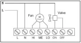
- Insert all wires into the correct terminals according to the wiring diagram.
- Attach the wired device to the 'A' points of the steel frame.
- Push the device into the junction box and confirm it is securely mounted.
Product Usage
On/Off Setting: When powered on, the display shows 'OFF'. Press the power button to enter the working interface. Pressing the power button again turns off the device.
Local Time Setting: Press and hold 'M' to enter time settings. Use 'M' to switch between Week, Hour, and Minute. Use the arrow buttons to adjust values. Press 'M' or wait 15 seconds to save.
Working Mode: Press 'M' to enter mode settings. Use arrows to switch between Cooling, Heating, and Ventilation modes. Press 'M' or wait 15 seconds to confirm.
Fan Speed: In normal display, press the fan button to cycle through Low, Medium, High, and Auto speeds. Press 'M' or wait 15 seconds to confirm.
Parameter Settings
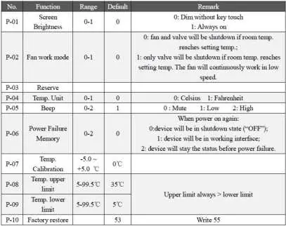
Under the shutdown state, press and hold 'M' to enter the parameter setting menu. Enter the password 5138 and press 'M' to access the menu. Parameters include screen brightness, fan work mode, temperature units, beep settings, power failure memory, and temperature calibration.
Troubleshooting
If network installation does not work as expected:
- Ensure the device is in factory reset state before including.
- If inclusion fails, exclude the device first, then try again.
- Verify that both devices use the same frequency.
- Remove all dead devices from associations to prevent delays.
- Ensure there are enough mains-powered devices to support the mesh network.
Technical Specifications
- Power Supply: AC85V~260V, 50/60HZ
- Resistive Load: 3A
- Z-Wave Frequency: 868.42MHz (EU)
- Working Environment: 0~55°C; less than 95% RH (Non-condensation)
- Temperature Setting: 5~35°C (Adjustable)
- Dimensions: 86 x 86 x 42mm
Practical help
Common problems
Inclusion fails
Ensure the device is in factory default state (exclude before include), check that both devices use the same frequency, and remove dead devices from associations.
Device not responding
Check power supply and ensure wiring connections are correct.
Before use
- Cut off power supply at circuit breaker before installation.
- Ensure the device is in factory default state for Z-Wave inclusion.
- Verify wiring matches the provided diagram.
- Ensure the device is installed indoors at approximately 1.5m height.
- Check that the installation location is away from direct sunlight or heat sources.
Specs in practice
- Power Supply
- AC85V~260V, 50/60HZ
- Resistive Load
- 3A maximum load
- Z-Wave Frequency
- 868.42MHz (EU region)
- Working Environment
- 0~55°C; less than 95% RH (Non-condensation)
Images and diagrams
- Wiring diagram shows connections for L (Line), N (Neutral), Fan (HI, ME, LO), and Valve (ON, OFF).
Model compatibility
- Designed for 2-pipe Fan coil systems.
- Requires a Z-Wave controller for network inclusion.

Manual page author
David Miller
Documentation analyst
Organizes user manual content into clear summaries, with attention to model details, product context, and everyday usability.