Tools / Grinding Tools
Hilti AG 230-20D Angle Grinder User Manual
Quick guide for the Hilti AG 230-20D angle grinder. Includes setup, accessory mounting, operation, safety warnings, and troubleshooting.
PDF source: polski · summary: English
Quick answers from the manual
Quick answer
- The Hilti AG 230-20D is a hand-held electric angle grinder designed for cutting and grinding metallic materials without water. It is intended for dry grinding and cutting only. p. 11, 22
Key actions
- Fitting the guard p. 13, 24
- Fitting an accessory tool p. 13, 24
First start
- Switching on p. 14, 25
Show 3 more answers Show less
Problems and fixes
Tool doesn't start
Check power supply, check cable/plug, check carbon brushes, or reset the restart interlock.
p. 15, 26Technical specifications
| Parameter | Value | Meaning | Pages |
|---|---|---|---|
| Weight | 5.3 kg | Weight in accordance with EPTA procedure 01 | p. 12, 23 |
| Maximum disc diameter | 230 mm | Maximum disc diameter | p. 12, 23 |
Where to find it in the PDF
- Product Overview p. 2
- Assembly p. 3
Table of contents
Manual images
Click an image to enlargeQuick guide from the manual
The Hilti AG 230-20D is a hand-held electric angle grinder designed for cutting and grinding metallic materials without the use of water. It is intended for dry grinding and cutting only. Before use, ensure the tool is in perfect working order and that you have read all safety instructions.
Product Overview
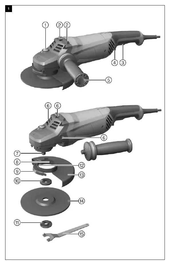
The tool features an arbor lockbutton, on/off switch with safety trigger, side handle, and a protective guard. The guard is keyed to ensure only compatible guards can be fitted.
Assembly

Fitting the side handle
Screw the side handle into one of the threaded bushings provided on the tool head.
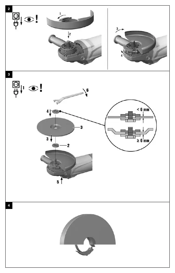
Fitting the guard
- Release the clamping lever.
- Fit the guard onto the arbor collar so that the keyed locating lug engages in the recess provided.
- Turn the guard to the desired position.
- Secure the guard by closing the clamping lever.
Operation
Fitting an accessory tool
- Disconnect the supply cord plug from the power outlet.
- Clean the clamping flange and the clamping nut.
- Fit the clamping flange onto the arbor.
- Fit the accessory tool.
- Screw on the clamping nut corresponding to the type of accessory tool fitted.
- Press and hold down the arbor lockbutton.
- Use the pin wrench to tighten the clamping nut securely, then release the arbor lockbutton and remove the wrench.
Switching on and off
To switch on, plug the tool into the power outlet, press the safety trigger to unlock the on/off switch, and press the on/off switch as far as it will go. To switch off, release the on/off switch.
Maintenance and Care
Always unplug the tool before performing any care or maintenance. Clean the air vents regularly with a dry brush. Use only a slightly damp cloth to clean the casing; do not use silicone-based cleaning agents. Regularly check all visible parts and controls for damage.
Troubleshooting
If the tool does not start, check the power supply, the supply cord, and the plug. If the tool is overloaded, release the on/off switch and allow the tool to run at no load for approximately 30 seconds. If the tool does not achieve full power, ensure the extension cord has an adequate conductor cross-section.
Manufacturer information
Hilti Corporation
Practical help
Common problems
Tool doesn't start
Check power supply, check cable/plug, check carbon brushes, or reset the restart interlock by switching the tool off and on again.
Tool doesn't work
Tool is overloaded. Release the on/off switch and press it again, then allow the tool to run at no load for approx. 30 seconds.
Tool does not achieve full power
The extension cord conductor cross-section is inadequate. Use an extension cord with an adequate conductor cross-section.
Before use
- Check that the guard is correctly fitted and adjusted.
- Ensure the side handle is securely attached.
- Check that the disc is compatible and undamaged.
- Verify power supply voltage matches the tool's rating plate.
Show more Show less
Specs in practice
- Max disc diameter
- 230 mm
Images and diagrams
- The product overview diagram identifies the arbor lockbutton, on/off switch, safety trigger, side handle, and guard components.
- The assembly diagram shows the sequence for fitting the guard and the accessory disc.

Manual page author
Michael Turner
Technical manual editor