Garden / Electric Fencing
Horizont 14495E Fence Voltmeter 7 LED User Manual
Quick guide for the Horizont 14495E Fence Voltmeter 7 LED. Learn how to measure fence voltage, interpret LED indicators, and replace the 9V battery.
Table of contents
Quick guide from the manual
The Horizont 14495E is a handheld fence tester designed for quick voltage checks. It does not require external earthing, as the user's body acts as the reference point. Always ensure your index finger is placed in the recess on the underside of the device during measurement.
Device Overview
The device features a control button, a battery status indicator, and a 6-LED display to show the voltage level of the fence. The device is powered by a 9V block battery.
Operation
To measure the voltage of your electric fence:
- Place the fence tester contact point against the fence material.
- Place your index finger in the recess on the underside of the device to ensure proper grounding.
- Press and hold the control button.
- Observe the LED display to read the voltage level.
Battery Replacement
The device operates on a 9V block battery. If the battery control indicator (marked with 3) lights up red, the battery must be replaced.
Voltage Indicators
The device uses 6 LEDs to indicate the voltage level:
- 10.000 - 6.000 V: Green light
- 6.000 - 4.000 V: Green light
- 4.000 - 2.000 V: Green light
- Below 2.000 V: Red light
Manufacturer information
horizont group gmbh
Practical help
Common problems
Battery indicator is red
Replace the 9V battery immediately.
No voltage reading
Ensure your index finger is firmly placed in the recess on the underside of the device to provide a reference point (earthing).
Voltage reading below 2000V
Check the fence for shorts, vegetation touching the wire, or damaged insulators.
Before use
- Ensure a 9V battery is installed.
- Ensure the fence material is accessible.
- Place index finger in the recess on the underside of the device before pressing the button.
Specs in practice
- 10.000 - 2.000 V
- Normal operating range for electric fences (Green LED).
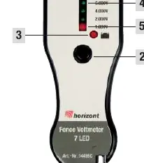
Images and diagrams
- 1: Fence contact point
- 2: Control button
- 3: Battery indicator
- 4: Voltage LED scale
- 5: Low voltage indicator (<2000V)
Model compatibility
- Compatible with standard electric fence materials.
- Requires 9V block battery.

Manual page author
Emily Carter
User documentation editor
Prepares concise manual descriptions and highlights the most useful setup, operation, and maintenance information for readers.