Industrial / Testing Equipment
Huazheng HZBZ-IV Automatic Comprehensive Transformer Test Bench Operating Instructions
Comprehensive operating instructions for the Huazheng HZBZ-IV Automatic Transformer Test Bench. This guide covers system configuration, test procedures, safety protocols, and technical specifications for transformer testing.
Table of contents
Manual images
Click an image to enlargeQuick Guide from the Manual
The Huazheng HZBZ-IV is an automated test system designed for routine, type, and special tests of 11–33 kV class distribution transformers. The system utilizes a PLC core and industrial control computer for automated testing, data management, and protection. Before operation, ensure the power supply is 380V (50Hz) with a capacity of at least 500A and that the site grounding resistance is less than 0.5 ohms.
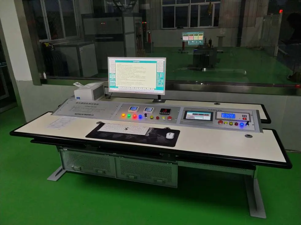
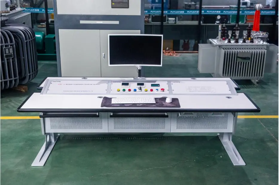
System Overview
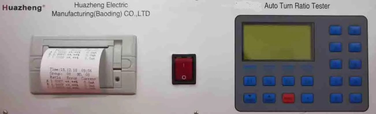
The system architecture consists of a master control console, a high/low voltage control cabinet, and various test instruments. It supports multiple test items including transformation ratio, DC resistance, no-load loss, induced overvoltage withstand, and temperature rise tests.
Operating Procedures
The system is operated via the integrated test software on the industrial control computer. The general workflow involves:
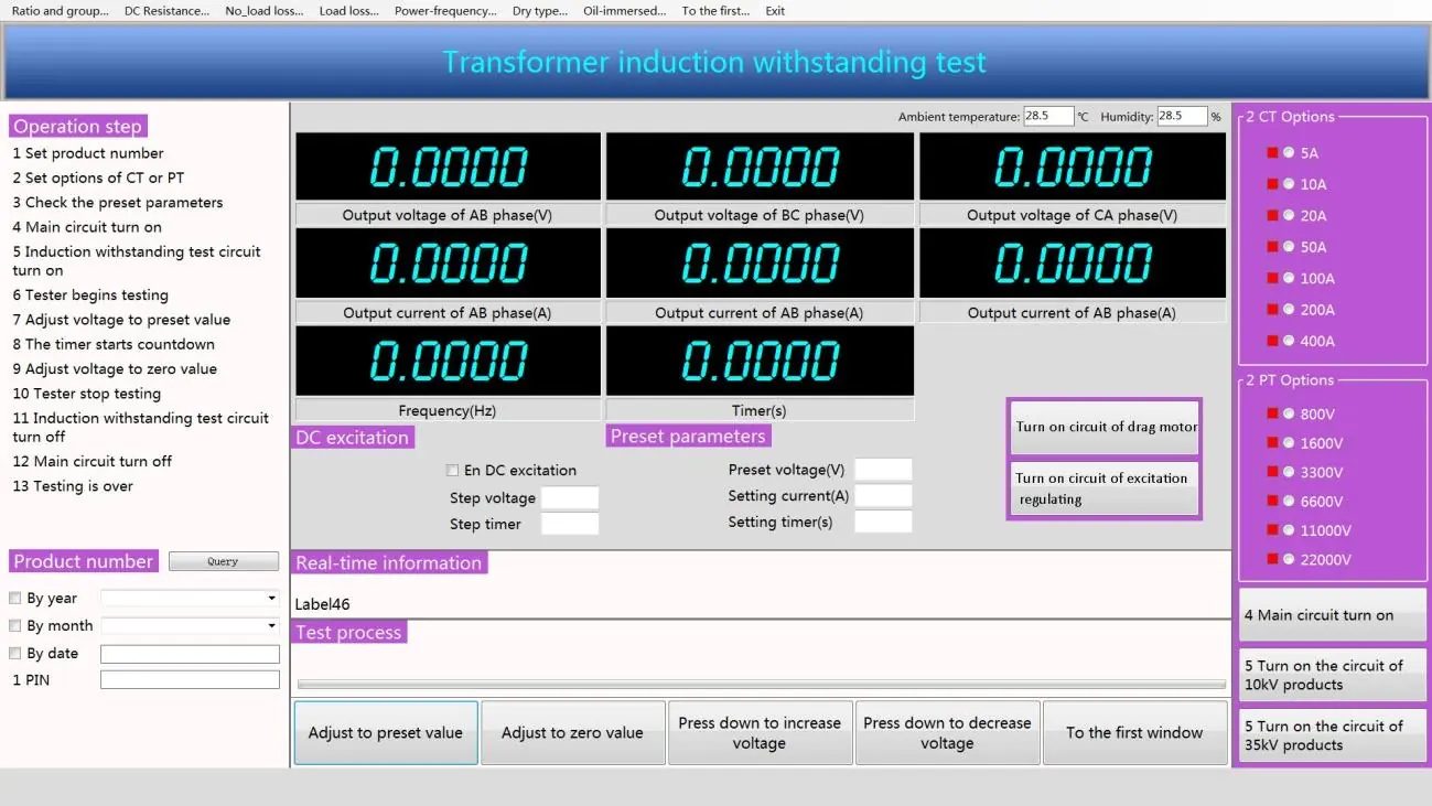
- Setting the product number and test parameters in the software.
- Configuring the test circuit (CT/PT options).
- Turning on the main circuit and specific test circuits.
- Adjusting voltage to the preset value using the software interface.
- Monitoring real-time data and waveforms.
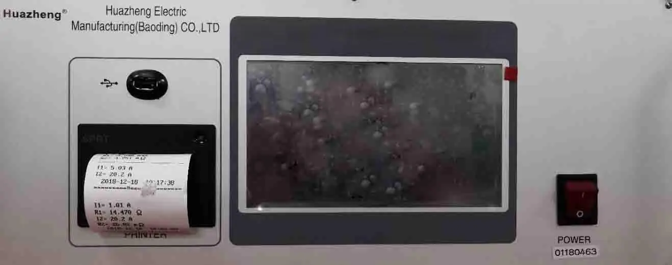
- Saving test data and generating reports automatically.
Safety and Protection
The system includes multiple layers of protection to ensure operator and equipment safety:
- Emergency Stop: Physical button on the console to immediately disconnect power.
- Zero Boost Protection: The system prevents power transmission unless the voltage regulator is at the zero position.
- Overcurrent/Overvoltage Protection: Automated monitoring of voltage and current signals; the system suspends operation if safety margins are exceeded.
- Warning Systems: Alarm lights and bells indicate test status.
Installation Requirements
- Power Supply: Three-phase, 380V, 50Hz, current capacity not less than 500A.
- Grounding: Site grounding resistance must be less than 0.5 ohms.
- Infrastructure: It is recommended to pre-ditch cable trenches in the control room and equipment area during civil construction.
Maintenance and Quality Assurance
The supplier provides a lifetime warranty policy with a one-year free warranty period for foreign countries, starting from the date of acceptance. Regular inspection of the system, including cable connections and grounding, is essential for reliable performance.
Manufacturer information
Huazheng Electric Manufacturing (Baoding) Co., Ltd.
Practical help
Common problems
Voltage regulator not at zero position
The system will not allow power transmission. Manually or automatically return the regulator to the zero position before starting.
Measurement exceeds safety margin
The system will automatically suspend step-up operation, issue a warning, and may trigger an emergency stop to protect equipment.
Grounding resistance too high
Ensure site grounding resistance is less than 0.5 ohms to maintain system integrity and safety.
Before use
- Verify power supply is 380V, 50Hz, and >500A.
- Check that site grounding resistance is < 0.5 ohms.
- Ensure the voltage regulator is in the zero position.
- Confirm all test cables are securely connected.
- Ensure the emergency stop button is accessible and functional.
Specs in practice
- Transformer Capacity
- Supports testing for transformers ranging from 2.5KVA up to 10000KVA, depending on voltage class.
- Primary Voltage
- Compatible with transformers below 33.0 kV.
- Output Frequency
- 150Hz for frequency multiplication generator tests.
Images and diagrams
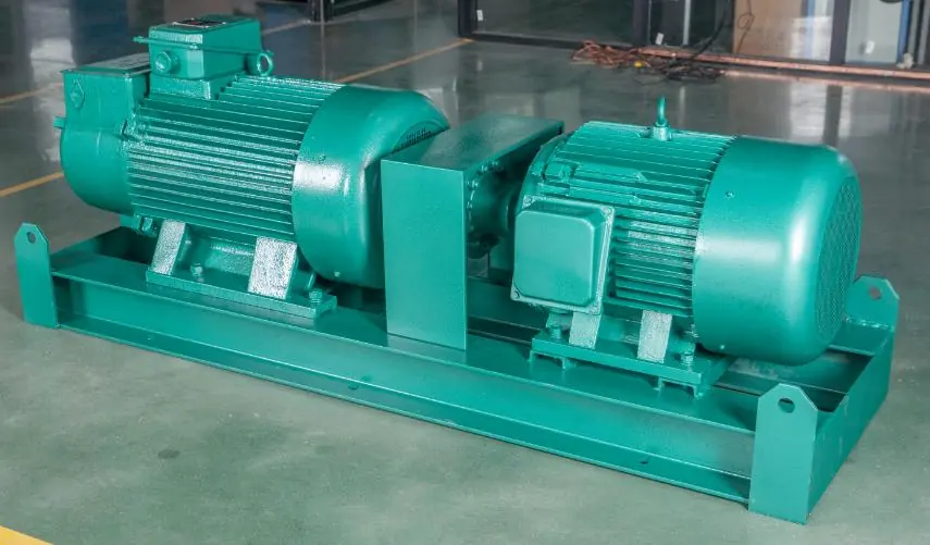
- The control loop diagram illustrates the signal flow from the power supply through the test bench, voltage regulator, intermediate transformer, and current transformer to the transformer under test.
Model compatibility
- Designed specifically for 11-33kV class distribution transformers.

Manual page author
Michael Turner
Technical manual editor
Reviews PDF manuals for structure, safety notes, and practical product details so readers can find the right information quickly.