Industrial / Testing Equipment
User Manual for OFITE 171-193-6K Permeability Plugging Tester
Quick guide for the OFITE 171-193-6K Permeability Plugging Tester. Includes setup, testing procedures for PPT and LCM, maintenance, and safety instructions.
Table of contents
Manual images
Click an image to enlargeQuick Guide from the Manual
The Permeability Plugging Tester (PPT) is designed for filtration tests on plugging materials. Key operational steps include preheating the heating jacket to 10°F above the target temperature, inspecting and greasing all O-rings, and ensuring the pressure release valve on the pump is closed before starting. Always use Carbon Dioxide or Nitrogen for pressurization; never use compressed air, oxygen, or nitrous oxide.
Safety Precautions
- Temperature: The heating jacket and test cell become extremely hot. Use protective clothing.
- Pressure: Do not exceed the maximum working pressure of 6,000 PSI (41.4 MPa).
- O-Rings: Use Viton 75D (black) for tests up to 400°F and Viton 90D (green) for tests up to 500°F. Inspect for damage before every test.
- Corrosion: Inspect the cell body and caps for corrosion before and after each test.
Equipment Assembly
The cell assembly involves placing O-rings on the shoulder inside the cell body and around the cell cap. Apply anti-seize compound to the threads of the cell caps. For the piston, ensure the set screw on the bleeder valve is loose during assembly, then tighten it after the piston is in place. Ensure all quick-connect fittings are fully engaged until they click.
Testing Procedures
For LCM Testing: Fill the cell with no more than 250 mL of test fluid. Stroke the pump until the fluid level reaches the O-ring shoulder. Assemble the receiver, ensuring the filter is in place, and fill the void space with water before starting.
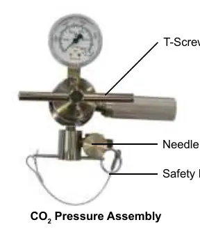
For PPT Testing: Stroke the pump until the T-handle rises approximately 1.5 inches. Pour test fluid into the cell, keeping the level just below the O-ring shoulder. Fill the outlet valve stem assembly with base fluid before attaching the back pressure receiver.
Data Analysis
To compare results to a standard filtration test (which has a 7.1 in² area), double the total filtrate volume collected (VF = 2 * V30). Spurt loss can be calculated using the formula: V1 = 4 * V7.5 - 2 * V30.
Maintenance and Troubleshooting
Clean and dry all components with water and soap after use. Periodically check for leaks by pressurizing the cell and immersing it in water. If the regulator malfunctions, symptoms like gas leaks at the outlet or inconsistent readings often indicate a need to replace the regulator or gauge.
Manufacturer information
OFI Testing Equipment, Inc.
Practical help
Common problems
Gas leak at regulator outlet
Replace the regulator (indicates seat leak or creep).
Outlet pressure increases while downstream valves are closed
Replace the regulator (indicates seat leak or creep).
Gas leak from spring housing case
Replace the regulator (indicates diaphragm failure).
Inconsistent repeat readings
Replace the regulator (seat sticking) or the pressure gauge (physical damage).
Before use
- Inspect all O-rings for nicks, cuts, or brittleness.
- Apply a thin film of grease to all O-rings.
- Preheat the heating jacket to 10°F (6°C) above the test temperature.
- Soak ceramic disks in base fluid for at least 10 minutes (for PPT tests).
- Ensure the pressure release valve on the pump is closed.
- Verify the correct O-ring material (Viton 75D for <400°F, Viton 90D for <500°F).
Specs in practice
- Maximum Pressure
- 6,000 PSI (41.4 MPa).
- Maximum Temperature
- 500°F (260°C).
- Heater Power
- 800W.
- Filtration Area
- 3.55 in² (22.9 cm²).
Images and diagrams
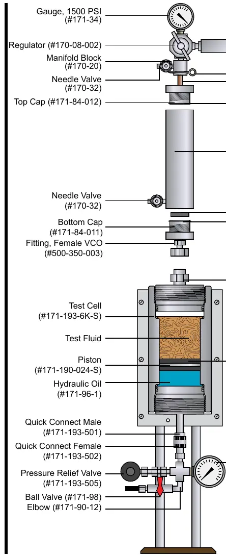
- The Permeability Plugging Tester diagram shows the vertical arrangement of the pressure gauge, regulator, receiver, and test cell.
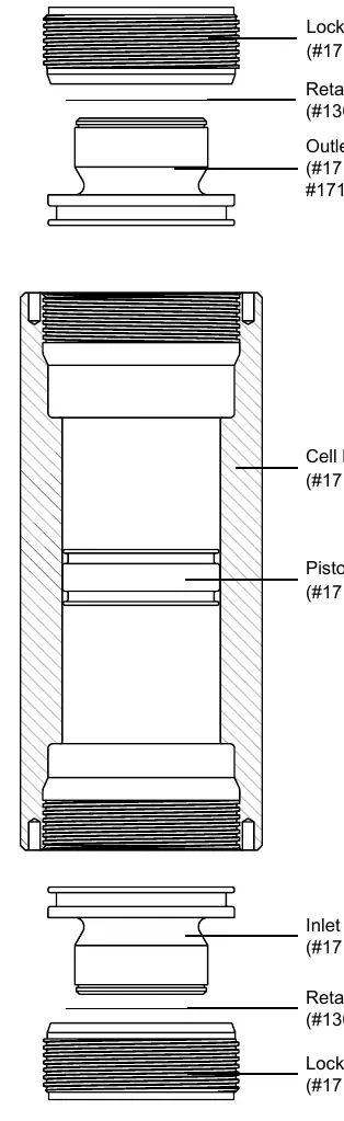
- The Test Cell diagram details the stacking order of the locking screw, retaining ring, outlet cap, cell body, piston, and inlet cap.
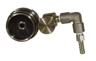
- The Outlet Valve Stem Assembly diagram illustrates the connection points for the back pressure receiver, ball valve, and cell cap.
Model compatibility
- Use only Carbon Dioxide or Nitrogen for pressurization.
- Do not use Nitrous Oxide, Oxygen, or compressed air.
- Viton 75D O-rings are for tests up to 400°F.
- Viton 90D O-rings are for tests up to 500°F.

Manual page author
Michael Turner
Technical manual editor
Reviews PDF manuals for structure, safety notes, and practical product details so readers can find the right information quickly.