Industrial / Testing Equipment
User Manual for Micsig DP Series High Voltage Differential Probe
Comprehensive user guide for the Micsig DP Series High Voltage Differential Probes. Includes operation steps, safety precautions, calibration procedures, and technical specifications for models DP700 through DP7002.
Table of contents
Manual images
Click an image to enlargeQuick Guide
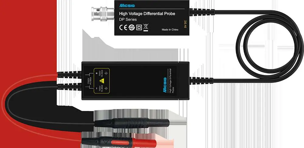
The Micsig DP Series High-Voltage Differential Probes are designed for high-speed differential voltage measurements, ideal for EV power systems, solar inverters, and switching power supplies. They feature selectable bandwidths, overload protection, and a standard BNC interface compatible with major oscilloscope brands.
Safety Precautions
- Do not allow non-professionals to open the product casing.
- Do not operate the device while the case is open.
- Avoid touching any bare metal parts during testing.
- Disconnect the power supply and circuit immediately if an over-range condition occurs.
- Do not use the probe in flammable or explosive environments.
Operation Steps
- Power the probe: Use the standard adapter provided.
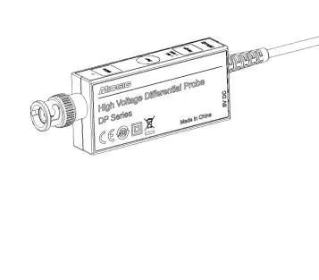
- Connect to oscilloscope: Connect the BNC end of the probe to the oscilloscope channel. Ensure the oscilloscope is properly grounded.
- Select Range: Choose the appropriate voltage range based on the signal.
- Connect the DUT: Use the provided clips or hooks to connect to the Device Under Test (DUT). If an over-voltage alarm occurs, disconnect immediately.
- Oscilloscope Settings: Set the oscilloscope input impedance to 1MΩ and adjust the channel attenuation ratio accordingly.
Note: Avoid using extension leads if possible, as they can increase the noise floor. If extension leads are necessary, twist them together to reduce noise, and ensure the input frequency does not exceed 5MHz to avoid measurement errors.
Calibration and Maintenance
For accurate results, it is recommended to use the probe after a 10-minute warm-up period. To calibrate the probe:
- Short-circuit the input ends.
- Power on the device.
- Press the "Zero" button.
- The 5MHz LED light will flash. A single "Di" sound indicates successful calibration.
- If you hear a "Di Di Di" sound, the calibration failed and must be repeated.
Appearance
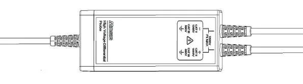
The DP differential probe consists of two main parts: the Control Module and the Signal Box. The Control Module features the 5MHz bandwidth limit button, Auto Zero button, and Range selection button with corresponding LED indicators. The Signal Box is used for connecting to the DUT.
Technical Specifications
The DP series includes multiple models (DP700, DP702, DP1500, DP1502, DP3000, DP3002, DP7000, DP7002) with varying bandwidths (100MHz/200MHz) and attenuation ratios (e.g., 20X/200X, 50X/500X, 100X/1000X). Maximum differential input voltage ranges from 70V to 7000Vpk depending on the model.
Warranty
Micsig provides a 1-year warranty for the main body of the differential probe under normal use. Warranty service may be refused if the anti-counterfeiting label is altered, the device has been unauthorizedly disassembled, or if there is no valid sales voucher.
Manufacturer information
Shenzhen Micsig Technology Co., Ltd.
Practical help
Common problems
Overvoltage warning (Range LED flashes and beeps rapidly)
Immediately disconnect the power supply and circuit, then switch to a higher voltage range.
Calibration failed (Audible 'Di Di Di' sound)
Ensure input ends are short-circuited and repeat the calibration process by pressing the 'Zero' button.
High noise floor during measurement
Avoid using extension leads. If required, twist the leads together and ensure the input frequency does not exceed 5MHz.
Before use
- Ensure the oscilloscope is properly grounded.
- Set the oscilloscope channel input impedance to 1MΩ.
- Allow the probe to warm up for 10 minutes for accurate results.
- Perform probe calibration before starting measurements.
Images and diagrams
- Control Module: Contains the interface for calibration (Zero button), range selection, and bandwidth limiting.
- Signal Box: The component that connects directly to the test points using clips or hooks.
Model compatibility
- Compatible with all major oscilloscope brands via standard BNC interface.
- Oscilloscope bandwidth must be equal to or greater than the probe bandwidth.

Manual page author
Emily Carter
User documentation editor
Prepares concise manual descriptions and highlights the most useful setup, operation, and maintenance information for readers.