Hvac / Heat Pumps
IDEAL 61-357 / 61-347 Digital Multimeter Instruction Manual
Comprehensive operation and safety manual for the IDEAL 61-357 and 61-347 auto-ranging TRMS digital multimeters, covering measurement functions, safety procedures, and maintenance.
Table of contents
Manual images
Jump to the sectionProduct Overview
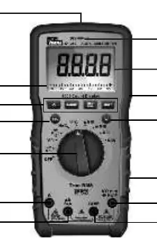
The IDEAL 61-357 and 61-347 are auto-ranging True Root Mean Square (TRMS) digital multimeters designed for professional use. These meters measure AC and DC current, voltage, frequency, resistance, continuity, capacitance, and diodes using test leads. They also feature a K-Type thermocouple input for temperature measurement and a non-contact voltage (NCV) sensor for detecting live voltage between 40V and 600V AC.
Safety Information
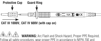
Warning: Arc Flash and Shock Hazard. Proper Personal Protective Equipment (PPE) is required. Always follow NFPA 70E safety standards. Before use, inspect the meter and test leads for damage. Never use the meter if the case is cracked or if the leads show exposed metal. Ensure fingers are kept behind the tactile barrier on the probes during measurement. Always disconnect test leads from the circuit before opening the battery compartment.
Operation
The meters feature a rotary dial for function selection and a SEL button to toggle between sub-functions (e.g., AC/DC, continuity/resistance). The 61-357 model includes an analog bar graph for quick visual reference. The NCV function allows for non-contact detection of live conductors. Data hold, MAX/MIN recording, and relative (REL) measurement features are available to assist in complex testing scenarios. The meters are IP52 rated for dust and water resistance.
Maintenance and Service
Regular inspection of the meter, test leads, and thermocouple is essential for accurate readings. If the meter is not in use for more than one month, remove the batteries to prevent leakage. The meter uses two specific fuses for current protection: a 600mA/1000V fuse for the mA/uA terminal and an 11A/1000V fuse for the 10A terminal. Only use specified replacement fuses to maintain safety and performance. Clean the exterior with a damp cloth and mild detergent; do not use abrasives or solvents.
Disposal
This product must not be disposed of as unsorted municipal waste. It should be recycled in accordance with local regulations. Used batteries must be returned to authorized collection points to prevent environmental harm.
Practical help
Common problems
LCD displays 'LEAd'
Test lead is inserted into an amperage terminal, but the rotary dial is not set to the correct amperage position.
LCD displays 'FUSE'
The internal fuse for the selected current range is blown and requires replacement.
Inaccurate readings
Check for low battery indicator. Replace batteries if voltage is below 3.6V.
Ghost or stray voltage readings
Use the LoZ (Low Impedance) setting on the 61-357 to eliminate induced voltage coupling.
Before use
- Visually inspect the meter case for cracks.
- Check test leads for damaged insulation or exposed metal.
- Verify the battery door is closed and secured.
- Ensure the correct function and range are selected for the application.
- Confirm the circuit is de-energized before measuring resistance or continuity.
- Wear appropriate PPE as per NFPA 70E.
Specs in practice
- CAT III / CAT IV
- Measurement categories indicating the meter's ability to withstand voltage transients in specific electrical environments.
Images and diagrams
- The rotary dial (10) is the primary control for selecting measurement functions.
- Input terminals (6, 7, 8, 9) are color-coded and labeled for specific measurement types.
- The NCV sensing point (13) is located at the top center of the meter.
- The tactile barrier (3) must be kept between the user's fingers and the probe tips.
Model compatibility
- Intended for use with IDEAL TL-757 test leads or equivalent rated for CAT IV 600V / CAT III 1000V.
- Requires 3 x 1.5V AAA batteries.
- 61-357 model includes LoZ and analog bar graph features not present on the 61-347.

Manual page author
Michael Turner
Technical manual editor
Reviews PDF manuals for structure, safety notes, and practical product details so readers can find the right information quickly.