Hvac / Heat Pumps
IDEAL 61-357 and 61-347 Digital Multimeters Operation and Safety Manual
Comprehensive operation and safety manual for the IDEAL 61-357 and 61-347 True RMS Digital Multimeters, covering setup, measurement functions, maintenance, and safety guidelines.
Table of contents
Manual images
Jump to the sectionProduct Overview
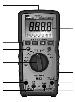
The IDEAL 61-357 and 61-347 are auto-ranging True RMS digital multimeters designed for professional use. These meters are capable of measuring AC and DC current, voltage, frequency, resistance, continuity, capacitance, and diodes. Additionally, they feature a K-Type thermocouple input for temperature measurement and a non-contact voltage (NCV) sensor for detecting live voltage between 40V and 600V AC.

Safety Information
Warning: These meters are intended for use by qualified electricians. Always follow NFPA 70E safety standards. Before use, inspect the meter and test leads for damage. Never use the meter if the case is cracked or if the battery door is not secured. Always keep fingers behind the tactile barrier on the probes during measurements. Ensure the meter is used only in environments for which it is rated (CAT III 1000V / CAT IV 600V).
Operation and Features
The meters feature a large LCD display, a function dial for selecting measurement modes, and a SEL button to toggle between sub-functions. Key features include a Data Hold function to lock readings, a MAX/MIN mode to record variations, and a REL (Relative) mode. The 61-357 model also includes a LoZ (low impedance) setting to eliminate ghost voltage readings and an analog bar graph for quick visual reference. The meters are IP52 rated for dust and water resistance.
Maintenance and Troubleshooting
Regular maintenance is essential for accurate readings. Inspect the battery compartment monthly for signs of degradation. If the low battery indicator appears, replace the batteries immediately. If the meter displays 'LEAd', check that test leads are in the correct terminals. If 'FUSE' is displayed, the internal fuse is blown and must be replaced with the specified ceramic fuse. Always disconnect test leads before opening the battery or fuse compartment.
Disposal
This product must not be disposed of as unsorted municipal waste. Please follow local regulations for the disposal of electronic equipment and batteries to protect the environment.
Practical help
Common problems
LCD displays 'LEAd'
Test leads are inserted into an amperage terminal, but the rotary switch is not set to the correct amperage position, or vice versa.
LCD displays 'FUSE'
The internal fuse for the selected amperage terminal is blown and requires replacement.
Ghost or stray voltage readings
Use the LoZ (Low Impedance) setting on the 61-357 model to eliminate induced voltage influence.
Low battery indicator appears
Replace batteries immediately to ensure measurement accuracy and safety.
Before use
- Visually inspect the meter case for cracks.
- Check test leads for damaged insulation or exposed metal.
- Verify the battery door is closed and secured.
- Ensure the meter is set to the correct function and range.
- Confirm the environment is within the meter's safety rating (CAT III/IV).
- Wear appropriate PPE as required by NFPA 70E.
Specs in practice
- CAT III 1000V / CAT IV 600V
- Safety rating indicating the meter's ability to withstand voltage transients in specific electrical environments.
Images and diagrams
- The rotary dial selects the primary measurement function.
- Input terminals are color-coded and labeled for specific functions (Amps, mA/uA, COM, Volts/Ohms).
- The NCV sensing point is located at the top center of the meter.
- The tactile barrier on the probes prevents fingers from touching live conductors.
Model compatibility
- Designed for use with IDEAL TL-757 test leads or equivalent.
- Requires 3 x 1.5V AAA batteries.
- 61-357 includes LoZ and analog bar graph features not present on the 61-347.

Manual page author
Michael Turner
Technical manual editor
Reviews PDF manuals for structure, safety notes, and practical product details so readers can find the right information quickly.