Automotive / Exhaust Systems
JBA Performance Exhaust 1400S/1411S Cat4Ward Headers Installation Instructions
Installation guide for JBA Performance Exhaust Cat4Ward Headers (models 1400S and 1411S). Includes safety precautions, step-by-step removal and installation procedures, critical welding requirements for catalytic converters, and...
Table of contents
Manual images
Click an image to enlargeQuick guide from the manual
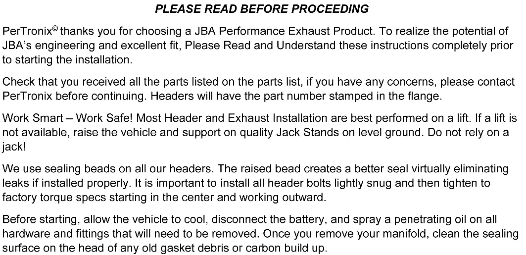
This installation requires welding. Before starting, ensure the vehicle is cool, the battery is disconnected, and you have access to a lift or quality jack stands. The installation involves removing factory manifolds, cutting the catalytic converter from the factory manifold, and welding it to the new JBA header. Always re-torque header bolts after 100 miles of driving.
Installation Overview
The installation process requires specific mechanical knowledge and welding capabilities. The catalytic converter is welded to the factory manifold and must be carefully removed and re-welded to the new JBA header to maintain emissions system integrity and legal road use.
Driver's Side Installation
- Remove front tires and inner fenders.
- On 16 & Newer vehicles, remove transmission/oil pan shields and Pyrometers.
- Unplug O2 sensors and unbolt factory exhaust from catalytic converters.
- Remove steering shaft (mark U-Joint positions first).
- Support the engine with a floor jack and wood block under the oil pan.
- Unbolt motor mount from frame and engine block, then lift engine approximately 1 inch.
- Remove heat shield and factory manifold nuts (be careful, they round off easily).
- Remove manifold/cat assembly.
- Mark 3/16 inch above the factory weld on the converter, then cut squarely.
- Temporarily install the new JBA header, lower the engine, and reinstall the motor mount.
- Align the header collector with the catalytic converter, tack-weld them together, then remove the assembly to finish welding.
- Reinstall the header/cat assembly using the supplied gasket.
Passenger Side Installation
- Remove the engine oil dipstick tube.
- If equipped, remove the oil cooler heat shield.
- Follow the same removal and installation steps as the driver's side (steps 2-18).
- Reinstall the oil dipstick tube.
- Ensure all wiring, fuel lines, transmission lines, and brake lines are clear of the headers.
Post-Installation Maintenance
- Reconnect the negative battery cable.
- Start the engine and check for leaks.
- Perform a test drive.
- Allow the engine to cool and re-torque the header bolts.
- Check and re-tighten the header bolts again after 100 miles.
Parts List
- (1) Driver Side Header Assembly
- (1) Passenger Side Header Assembly
- (2) Header gaskets
Practical help
Common problems
Nuts rounding off
Exercise extreme caution when removing the nuts attaching the factory manifold to the cylinder head as they round off easily.
Engine shifting
When removing motor mounts, use a floor jack with a block of wood under the oil pan to support the engine and prevent shifting.
Exhaust leaks
Ensure the catalytic converter is welded securely with no pinhole leaks. Re-torque header bolts after 100 miles.
Before use
- Allow the vehicle to cool completely before starting.
- Disconnect the battery.
- Spray penetrating oil on all hardware and fittings to be removed.
- Ensure you have a lift or quality jack stands on level ground.
- Verify all parts from the parts list are present.
- Ensure you have welding equipment available.
Model compatibility
- 1400S: 04-15 Nissan Armada, Titan, Infinity QX56.
- 1411S: 16-21 Nissan Armada, Titan, Infinity QX80; 11-13 QX56.

Manual page author
Michael Turner
Technical manual editor
Reviews PDF manuals for structure, safety notes, and practical product details so readers can find the right information quickly.