Automotive / Exhaust Systems
Installation Instructions for JBA Performance Exhaust 1685S Cat4Ward Headers
A comprehensive installation guide for the JBA Performance Exhaust 1685S Cat4Ward Headers designed for the 2011-2014 Mustang 5.0. Includes step-by-step procedures for driver and passenger side installation, parts list, and safety warnings.
Quick answers from the manual
Quick answer
- The JBA 1685S Cat4Ward Headers are designed for the 2011-2014 Mustang 5.0. Installation requires removing the factory exhaust manifolds, steering shaft (driver's side), and starter (passenger's side), and lifting the engine slightly to access motor mounts. p. 1, 2, 3
Key actions
- Lift the engine 2-3 inches to remove the motor mount stand. p. 2
- Use an E8 External Torx socket to remove manifold studs. p. 2
First start
- Start the engine, check for leaks, test drive, let cool, and re-torque header bolts. p. 3
Where to find it in the PDF
- Installation Steps p. 2, 3
Table of contents
Manual images
Click an image to enlargeQuick guide from the manual
This document provides installation instructions for the JBA 1685S Cat4Ward Headers on 2011-2014 Mustang 5.0 vehicles. Installation is time-consuming due to tight working areas. Ensure you have an E8 External Torx socket before beginning. Always work on a lift or use quality jack stands on level ground.

Parts List
- Driver’s Side Header Assembly
- Passenger’s Side Header Assembly
- Header flange gaskets
- 16x 10mm-1.5 header bolts
- 16x 10mm-1.25 header bolts
- 16x Header Bolt Washers
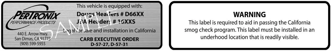
- CARB EO Sticker
Preparation
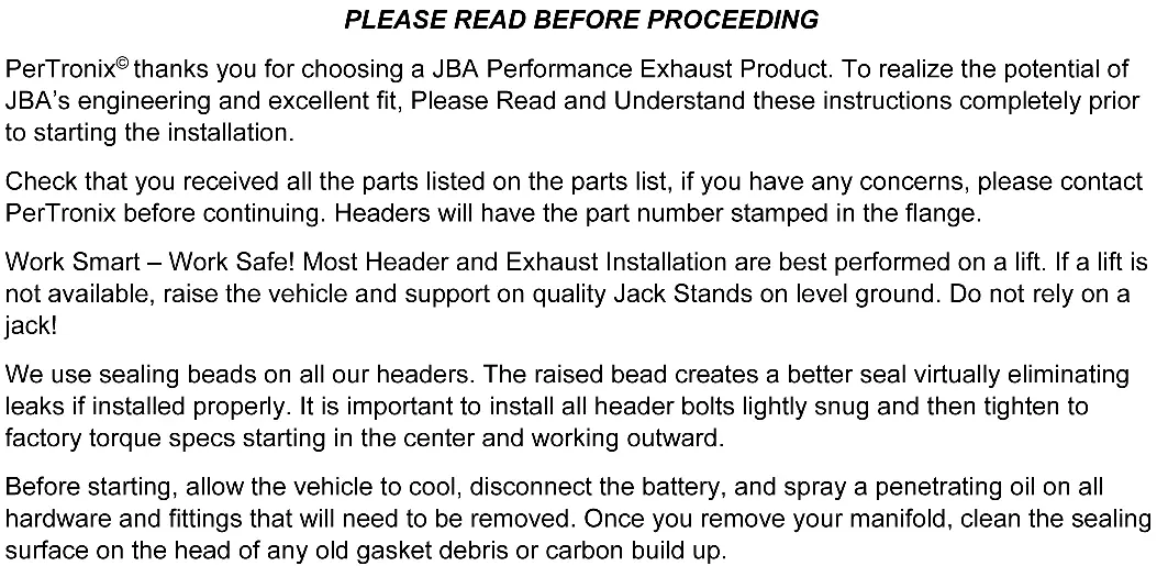
Before starting the installation, allow the vehicle to cool completely. Disconnect the battery. Spray penetrating oil on all hardware and fittings that need to be removed. Clean the sealing surface on the head of any old gasket debris or carbon build-up.
Installation - Driver's Side

- Remove the steering shaft from the U-Joint on the steering rack.
- Place a jack under the oil pan using a block of wood to spread the load. Lightly jack up the motor to remove weight from the motor mounts.
- Unbolt the large nut in the center of the motor mount from the top.
- From below, remove the 4 bolts holding the Aluminum motor mount stand to the engine block.
- Jack the motor up about 2-3 inches and remove the Aluminum motor mount stand.
- Unplug the O2 sensors.
- Remove the nuts holding the stock exhaust manifolds to the cylinder heads.
- Remove the manifold studs from the head using an E8 External Torx socket.
- Remove the O2 sensor from the stock manifold and install it into the JBA header using a small amount of anti-seize.
- Slip the supplied exhaust gasket into place and install the new JBA Header using the supplied bolts and washers. Important: Ford used two different thread pitches on the cylinder heads. Compare the supplied header bolts to your original studs to avoid stripping the heads.
- Tighten fasteners in an alternating sequence.
- Reinstall the motor mount stand, lower the motor, tighten all bolts, and reinstall the steering shaft.
Installation - Passenger's Side
- Remove the starter motor.
- Follow the same procedure as the driver's side for motor mounts and manifold removal.
- Install the JBA header.
- Re-install the starter, lower the engine, and tighten the lower mount bolts.
- Reinstall the factory catalytic converters using the original gaskets.
- Plug all 4 O2 sensors back in.
- Check to ensure adequate clearance on all brake lines, wire looms, and A/C lines.
- Reconnect the battery.
Post-Installation
Start the engine and check for leaks. Take the vehicle for a test drive. Once the engine has cooled, re-torque the header bolts. Periodically check and retighten the header bolts as part of routine maintenance.
Warranty and Compliance
This product is 50-state legal when installed on the specified vehicle per the manufacturer's application guide. The CARB EO sticker must be installed in a readily visible underhood location. The JBA Limited Warranty covers defects in materials and workmanship for one year to the original purchaser.
Practical help
Common problems
Tight working areas
Factory locking nuts can only be turned a small amount at a time; allow plenty of time for the installation.
Incorrect bolt thread pitch
Ford used two different thread pitches on cylinder heads. Compare the supplied header bolts to your original studs before installing to avoid stripping the heads.
Exhaust leaks
Use the sealing beads on the headers. Install bolts lightly snug, then tighten in an alternating sequence starting from the center and working outward.
Before use
- Allow the vehicle to cool completely
- Disconnect the battery
- Ensure you have an E8 External Torx socket
- Verify all parts from the parts list are present
- Use a lift or quality jack stands on level ground
Specs in practice
- 10mm-1.5 vs 10mm-1.25
- Two different thread pitches for header bolts; verify against original studs to avoid stripping the cylinder heads.
Model compatibility
- Fits 2011-2014 Mustang 5.0

Manual page author
Emily Carter
User documentation editor
Prepares concise manual descriptions and highlights the most useful setup, operation, and maintenance information for readers.