Automotive / Exhaust Systems
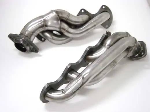
Installation Instructions for JBA Performance Exhaust Cat4Ward Headers 1676S / 1676S-1
Installation guide for JBA Performance Exhaust Cat4Ward Headers (models 1676S and 1676S-1). Includes step-by-step mounting instructions for Ford F-150 and F-250, parts list, and warranty information.
Quick answers from the manual
Quick answer
- These instructions cover the installation of JBA Cat4Ward Headers on Ford F-150 (1676S) and F-250 (1676S-1) trucks. The process involves removing the factory manifolds, cleaning the head surfaces, installing the new headers with supplied gaskets and hardware, and ensuring proper clearance for surrounding lines. p. 1, 2, 3
Key actions
- Tighten header bolts in an alternating sequence. p. 2, 3
- Re-torque header bolts after test drive. p. 3
First start
- Start the engine, check for leaks, and test drive. Let the engine cool and then re-torque the header bolts. p. 3
Maintenance and reset
- Periodically check and retighten the header bolts. p. 3
Technical specifications
| Parameter | Value | Meaning | Pages |
|---|---|---|---|
| Header Bolts | 8mm | Size of bolts used for header flange. | p. 3 |
| Collector Bolts | 3/8-16 x 2.5" | Size of bolts used for collector connection. | p. 3 |
Where to find it in the PDF
- Cover Page p. 1
- Passenger Side Installation p. 2
- Driver's Side Installation and Parts List p. 3
- Warranty Information p. 4
Table of contents
Manual images
Click an image to enlargeQuick guide from the manual
This document provides installation instructions for JBA Performance Exhaust Cat4Ward Headers, specifically models 1676S (2004-10 Ford F-150 5.4L 3V) and 1676S-1 (2005-10 Ford F-250 5.4L 3V). Before beginning, ensure the vehicle is cool, the battery is disconnected, and you have access to a lift or quality jack stands.
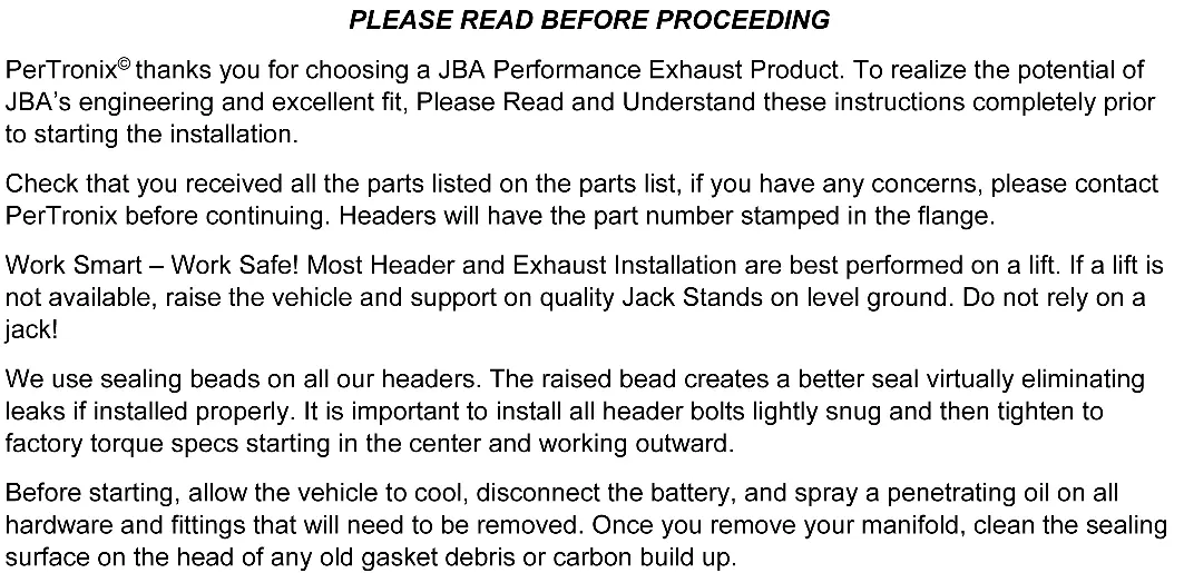
Preparation and Safety
- Safety First: Always use a lift if available. If not, raise the vehicle and support it on quality jack stands on level ground. Never rely solely on a jack.
- Preparation: Allow the engine to cool completely. Disconnect the battery. Spray penetrating oil on all hardware and fittings to be removed.
- Surface Cleaning: After removing the manifold, clean the sealing surface on the head of all old gasket debris or carbon buildup. Use a scraper or gasket removal agent, ensuring no debris enters the ports.
Passenger Side Header Installation
- From underneath, unbolt the factory exhaust system from the manifold collectors. Pry the exhaust system back about 1/2 inch to gain workspace. Spraying rubber exhaust hangers with WD-40 may assist.
- Remove the passenger side front tire and inner fender panel.
- Remove the starter.
- Place a jack with a board between the jack and the oil pan under the motor. Remove the motor mount nut (under the frame) and raise the engine approximately 1 inch. Remove the bolts holding the motor mount plate to the engine.
- Remove the nuts and studs attaching the manifold to the head, then remove the manifold.
- Remove the gasket and clean the head surface.
- Remove both studs from cylinder 2 and 3, and the top stud from cylinder 1.
- Slip the header over the frame from the top.
- Install the supplied gasket after the header is in place.
- Re-install studs on cylinder 1 and 2 only.
- Install supplied bolts and washers on cylinder 3.
- Reuse factory nuts on remaining studs. Tighten fasteners in an alternating sequence.
- Re-install the starter, bolt the motor mount plate to the motor, lower the motor, and tighten the lower mount bolts.
Driver's Side Header Installation
- From underneath, remove the nuts attaching the manifold to the head. Remove the engine oil dipstick, noting its insertion point. Remove the manifold.
- Remove the rear-most top manifold stud from the head.
- Clean the head surface of gasket material and carbon deposits.
- Slip the supplied head gasket over the studs, then install the header.
- Install the supplied bolt and washer into the rear-most top hole. Reuse factory nuts on remaining studs. Tighten in an alternating sequence.
- Reinstall the dipstick tube and dipstick.
- Apply O2 sensor-safe RTV silicone around the flares on the factory exhaust system. Reconnect the factory exhaust system to the new headers using the supplied 2-1/2 inch collector bolts.
- Verify that all wiring, fuel lines, transmission cooler lines, and brake lines are clear of the headers. Reroute or relocate components if necessary.
- Install the inner fender panel and front wheel.
- Reconnect the battery.
- Start the engine, check for leaks, and test drive. Let the engine cool and re-torque the header bolts. Periodically check and retighten bolts.
Parts List
- (1) Driver’s Side Header Assembly
- (1) Passenger’s Side Header Assembly
- (2) Header flange gaskets
- (3) 8mm Header Bolts
- (3) 8mm Lock washers
- (4) 3/8-16 x 2.5” Collector Bolts
- (4) 3/8-16 Nuts
- (1) CARB EO Sticker
Practical help
Common problems
Exhaust leaks
Ensure the sealing surface is clean of all old gasket material and carbon. Tighten header bolts in an alternating sequence and re-torque after the first test drive.
Clearance issues with lines/hoses
Check that all wiring, fuel lines, transmission cooler lines, and brake lines are clear of the headers. Reroute or relocate these components as necessary.
Before use
- Verify all parts from the parts list are present.
- Ensure the vehicle is on a lift or supported by quality jack stands.
- Allow the engine to cool completely.
- Disconnect the vehicle battery.
- Apply penetrating oil to hardware being removed.
Specs in practice
- 8mm Header Bolts
- Used for securing the header flange to the cylinder head.
- 3/8-16 x 2.5” Collector Bolts
- Used to connect the factory exhaust system to the new headers.
Model compatibility
- 1676S: Fits 2004-10 Ford F-150 5.4L 3V.
- 1676S-1: Fits 2005-10 Ford F-250 5.4L 3V.

Manual page author
Michael Turner
Technical manual editor
Reviews PDF manuals for structure, safety notes, and practical product details so readers can find the right information quickly.