Automotive / Exhaust Systems
Installation Instructions for JBA Performance Exhaust 1695S Cat4Ward Headers
Comprehensive installation guide for JBA Performance Exhaust 1695S Cat4Ward Headers. Includes step-by-step removal and installation procedures, parts list, and warranty information for 2007-14 Mustang GT500.
Quick answers from the manual
Quick answer
- This document provides installation instructions for JBA Performance Exhaust 1695S Cat4Ward Headers on 2007-14 Mustang GT500 vehicles. It includes a 29-step installation procedure and warranty information. p. 1, 2, 3, 4
Key actions
- Remove battery, air intake, strut tower brace, and exhaust components. p. 2
- Raise engine 3 inches to remove motor mounts and install headers. p. 2, 3
- Tighten header bolts in a crisscross pattern starting in the center. p. 3
First start
- Reconnect battery cables, start engine, and check for leaks. p. 3
- Allow engine to reach operating temperature and take a test drive. p. 3
Maintenance and reset
- Re-check header bolts after 100 miles when cool. p. 3
- Check header bolts at least a couple of times a year. p. 3
Technical specifications
| Parameter | Value | Meaning | Pages |
|---|---|---|---|
| Motor mount spacer | 1 1/4” X 3/8” | Aluminum spacer required for motor mount reinstallation. | p. 3, 4 |
Where to find it in the PDF
- Cover and Warnings p. 1
- Preparation and Removal Steps p. 2
- Installation Steps p. 3
- Parts List and Warranty p. 4
Table of contents
Manual images
Click an image to enlargeImportant Information
This document provides installation instructions for JBA Performance Exhaust 1695S Cat4Ward Headers designed for 2007-14 Mustang GT500 (5.4/5.8L) vehicles. These headers are designed to work with the Stock K Member. Note: If the motor has been lowered, these headers may not fit. This is a difficult, time-consuming installation; it is recommended to set aside a minimum of 20 hours for proper installation.
Installation Preparation
Before beginning the installation, ensure you have received all parts listed in the parts list. Work on a lift if possible; if not, use quality jack stands on level ground. Do not rely on a jack alone. Allow the vehicle to cool completely, disconnect the battery, and apply penetrating oil to all hardware and fittings that will be removed. Clean the sealing surface on the head of any old gasket debris or carbon build-up.

Installation Procedure
The installation involves a detailed removal and reinstallation process:
- Removal: Remove battery cables, battery, and battery tray. Disconnect air inlet hose, air box, and vacuum lines. Remove strut tower brace. Support exhaust pipes, release retaining clips, and remove the converter assembly. Remove steering coupler bolt. Raise the engine approximately 3 inches using a block of wood under the oil pan to remove motor mounts. Remove exhaust manifolds, dipsticks, and studs.
- Installation: Install the new JBA headers using the supplied gaskets and bolts. Tighten header bolts evenly in a crisscross pattern starting in the center. Reinstall motor mounts using the supplied 1 1/4" x 3/8" aluminum spacers. Reattach steering shaft, starter, EGR tube, and all sensors. Reinstall mid-pipes, cats, battery tray, and air intake components.
- Final Steps: Reconnect battery cables. Start the engine and check for leaks. Allow the engine to reach operating temperature and take a test drive. Re-check header bolts after 100 miles when cool.
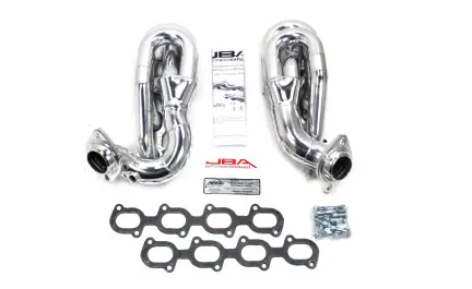
Parts List
- (1) Driver’s Side Header
- (1) Passenger’s Side Header
- (2) Header Flange Gaskets
- (16) Header Bolts
- (16) Header Bolt Lockwashers
- (2) 1 1/4” X 3/8” Aluminum motor mount spacer
- (1) CARB EO Sticker
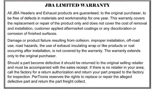
Warranty Information
JBA Headers and Exhaust products are guaranteed to the original purchaser to be free of defects in materials and workmanship for one year. This warranty covers replacement or repair of the product only and does not cover the cost of removal, installation, customer-applied coatings, or discoloration. Damage resulting from collision, improper installation, off-road use, road hazards, or the use of exhaust insulating wrap is not covered.
Practical help
Common problems
Headers do not fit.
Check if the motor has been lowered; these headers are designed for stock height and may not fit lowered motors.
Dipstick tube interference.
You may need to slightly tweak the dipstick tube to fit around the new header.
Header bolts loosening.
Header bolts can loosen over time due to heat cycles; check them at least a couple of times a year.
Before use
- Verify all parts from the parts list are present.
- Ensure the vehicle is on a lift or supported by quality jack stands on level ground.
- Allow the vehicle to cool completely before starting.
- Disconnect the battery.
- Apply penetrating oil to all hardware and fittings to be removed.
Specs in practice
- 1 1/4” X 3/8” Aluminum spacer
- Required for the motor mount assembly during reinstallation.
Model compatibility
- Designed for 2007-14 Mustang GT500 5.4/5.8L.
- Designed to work with the Stock K Member.

Manual page author
Michael Turner
Technical manual editor
Reviews PDF manuals for structure, safety notes, and practical product details so readers can find the right information quickly.