Automotive / Exhaust Systems
Installation Guide for JBA Performance Exhaust Cat4Ward Headers
Step-by-step installation guide for JBA Performance Exhaust Cat4Ward Headers (1625S series). Includes preparation, engine lifting procedures, A/C line relocation, and parts list for Mustang and SVT Cobra models.
Table of contents
Manual images
Click an image to enlargeQuick Guide
This document provides installation instructions for JBA Performance Exhaust Cat4Ward Headers. Key requirements include working on a lift or using quality jack stands, allowing the engine to cool completely before starting, and using anti-seize on all header bolts. A critical step for specific models involves relocating the air conditioning line to ensure proper clearance.
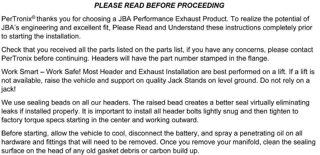
Preparation and Safety
Before beginning the installation, ensure you have all parts listed in the parts list. If you have concerns, contact the manufacturer before proceeding. Work smart and safe; if a lift is not available, raise the vehicle and support it on quality jack stands on level ground. Do not rely on a jack alone.
- Allow the vehicle to cool completely.
- Disconnect the battery.
- Spray penetrating oil on all hardware and fittings to be removed.
- Clean the sealing surface on the head of any old gasket debris or carbon build-up.
Installation Procedure

Passenger Side
- Unplug the Oxygen Sensors and disconnect the exhaust system from the catalytic converter assembly. Remove the converter assembly.
- Remove the Starter Motor.
- Remove the motor mount nut under the passenger side manifold.
- Place a block of wood between the oil pan and a jack. Remove the passenger side motor mount bolts and lift the motor approximately 1 inch.
- Remove the passenger side manifold and manifold studs. Note: On 96-97 Cobra installations, disconnect the air fitting from the front of the manifold.
- Relocate the air conditioning line by bending the soft aluminum line up slightly and reattaching it using the factory bracket into the alternate hole located approximately 2 inches above the original mounting hole.
- Apply anti-seize to all header bolts. Install the passenger side header using the supplied hardware and gasket. Reconnect the air fitting on 96-97 Cobra models.
- Lower the engine onto the motor mount and tighten the motor mount nut. Reinstall the starter.
Driver Side
- Disconnect the steering shaft from the steering rack and move it aside. Remove the Oil Filter.
- Disconnect the EGR tube from the driver side manifold. Remove the driver side manifold and dipstick tube. Remove all manifold studs. Note: On 96-97 Cobra installations, disconnect the air fitting from the front of the manifold.
- From underneath the vehicle, slip the new header into place. From the top, slide the dipstick tube through the header between the second and third tube. Guide the tube under the motor mount and into its hole.
- Loosely attach the EGR tube to the new header. Apply anti-seize to all header bolts. Install the driver side header using the supplied hardware and gasket. Reconnect the air fitting on 96-97 Cobra models.
- Tighten the EGR tube. Reconnect the steering shaft to the steering rack. Reinstall the dipstick tube and oil filter.
- Re-install the H-pipe using the supplied collector gasket on the passenger side. Apply a small bead of high-temperature, sensor-safe silicone around the dome on the driver side header for added leak protection, then reconnect the exhaust system.
- Reconnect the battery cable.
- Check that all bolts are tight. Ensure all wiring, fuel lines, transmission lines, and brake lines are clear of the headers.
- Start the engine, let it warm up, and check for leaks. Shut the engine off, let it cool, and re-check all fasteners.
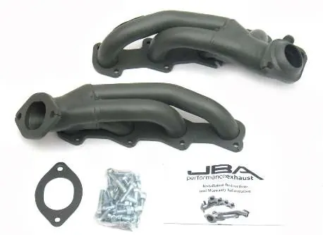
Parts List
- (1) Driver’s Side Header Assembly
- (1) Passenger’s Side Header Assembly
- (2) Header gaskets (Header to Head flange)
- (1) Base flange gasket
- (4) 3/8” Flat Washers
- (4) 3/8” Hex Nuts
- (18) 8mm x 1.25 Header bolts
- (18) 8mm Lock Washers
- (2) 3/8” x 1-1/2” Collector bolts
- (2) 3/8” x 2” Collector bolts
- (2) 3/8” Lock Washers
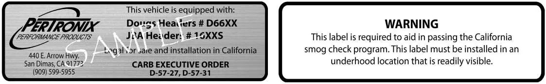
- (1) Carb Sticker
Warranty and Emissions
JBA Headers and Exhaust products are guaranteed to the original purchaser to be free of defects in materials and workmanship for one year. This warranty covers replacement or repair of the product only and does not cover removal, installation, or aftermarket coatings. Damage resulting from collision, improper installation, off-road use, road hazards, or the use of exhaust insulating wrap is not covered. This product has been granted a California Air Resources Board (CARB) Executive Order Exemption for specific vehicles.
Practical help
Common problems
Exhaust leaks
Apply a small bead of high-temperature, sensor-safe silicone around the dome on the driver's side header and ensure all bolts are tightened to factory specs.
Limited engine compartment space
Relocate the A/C line by bending the soft aluminum line slightly and using the alternate mounting hole located 2 inches above the factory hole.
Loose fasteners
Periodically check and retighten the header bolts after the initial installation and warm-up.
Before use
- Disconnect the battery.
- Allow the engine to cool completely.
- Use a lift or quality jack stands on level ground.
- Verify all parts from the parts list are present.
- Apply anti-seize to all header bolts.
- Ensure all wiring and lines are clear of the headers.
Images and diagrams
- The A/C line relocation diagram shows the factory A/C line being moved to an alternate hole on the frame rail to provide clearance for the new headers.
Model compatibility
- Compatible with Mustang and SVT Cobra 4.6L 2V/4V engines (1996-2004).
- Specific instructions apply for 96-97 Cobra models regarding air fitting disconnection.

Manual page author
Michael Turner
Technical manual editor
Reviews PDF manuals for structure, safety notes, and practical product details so readers can find the right information quickly.