Automotive / Exhaust Systems
Installation Instructions for JBA Performance Exhaust 1624S-2 Headers
Quick installation guide for JBA Performance Exhaust 1624S-2 headers. Includes step-by-step disassembly, modification, and installation procedures for 5.0L Mustang and Thunderbird models.
Table of contents
Manual images
Click an image to enlargeQuick guide from the manual
This document provides installation instructions for JBA Performance Exhaust headers, specifically model 1624S-2 (compatible with 86-93 5.0L Mustang/Cobra and 86-88 Thunderbird). The process involves removing factory exhaust manifolds, potentially modifying the oil dipstick tube, and installing the new headers using the provided hardware. Always ensure the vehicle is cool and properly supported on jack stands before beginning.
Safety and Preparation
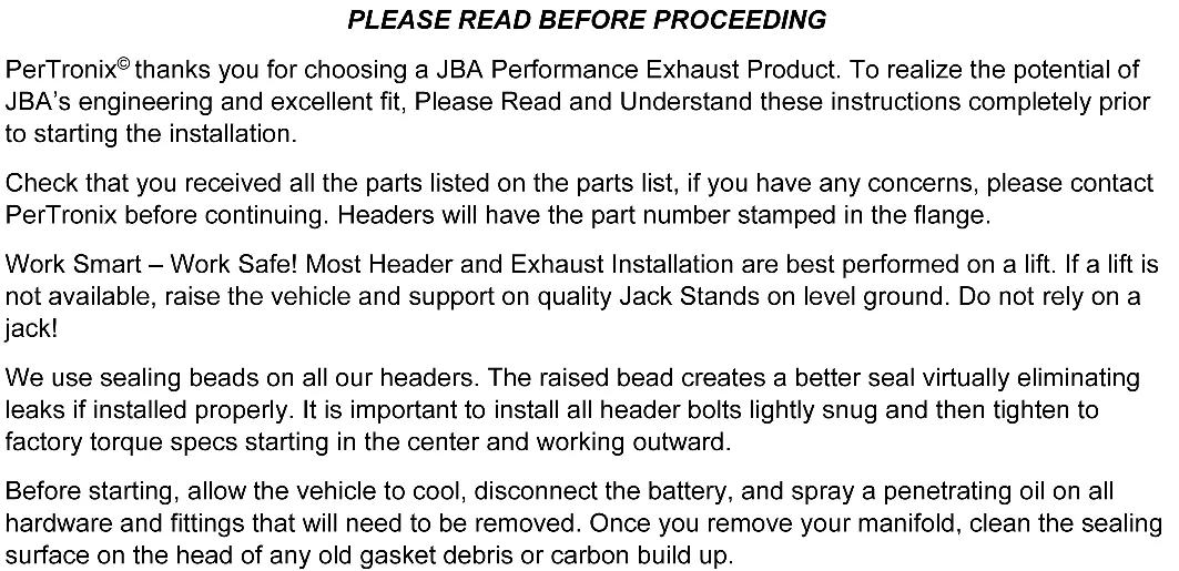
Before starting the installation, ensure you have all parts listed in the parts list. Work on a lift if possible; if not, use quality jack stands on level ground. Do not rely solely on a jack. Disconnect the battery and allow the engine to cool completely. Spray penetrating oil on all hardware to be removed. Clean the sealing surface on the cylinder head of any old gasket debris or carbon build-up.
Disassembly
- Unbolt the H-Pipe assembly from the factory header collector flanges. Ensure no pressure is placed on the O2 sensor wires; disconnect them if necessary.
- Unbolt the dipstick tube bracket from the engine and remove the dipstick tube. Discard the engine lift brackets.
- Unbolt the driver's side exhaust manifold and remove it. Clean the head surface of any gasket material or carbon deposits.
- If necessary, grind the oil dipstick tube mounting tab to clear the header tube. Once clearanced, clean the tube, apply a small amount of sensor-safe silicone around the end, and reinstall.
- Remove the passenger side EGR tube from the stock manifold. Unbolt the passenger side manifold and remove it. Clean the head surface and H-Pipe mating flange.
Installation
- From above, slip the driver's side header into position. Slide the gasket into place and install the supplied header bolts and lock washers. Anti-seize is recommended on aluminum heads. Tighten the bolts starting from the center and working outward.
- Repeat the positioning and installation process for the passenger side header. Use the 3/8" x 2" bolt with the spacer in the rear-most header bolt hole. The EGR tube tab will bolt to this bolt to space the tube out from its original location.
- Apply a light coating of Sensor Safe Hi-Temp Silicone to the collector dome on both headers. Install the supplied collector bolts into the collector flange holes from the topside. Have an assistant hold a wrench on the bolt head from the topside while tightening the nuts from the bottom.
- Reinstall the spark plug wires and looms, ensuring no wires rest against the headers.
- Reinstall the negative battery cable.
- Check that all bolts are tight. Ensure all wiring, fuel lines, transmission lines, and brake lines are clear of the headers and exhaust.
- Start the engine, let it warm up, and check for leaks. Shut the engine off, let it cool, and re-check that all fasteners are tight.
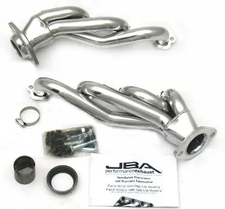
Parts List
- (1) Driver’s Side Header Assembly
- (1) Passenger’s Side Header Assembly
- (15) 3/8" x 1" header bolts
- (15) 3/8" Lock washers
- (1) 3/8" x 2" header bolt & lock washer
- (1) 1" tubular spacer
- (4) Collector Bolts & Nuts
- (2) Header gaskets
- (1) CARB Sticker
- (2) JBA Stickers
Practical help
Common problems
Dipstick tube interference
It may be necessary to grind the oil dipstick tube mounting tab to clear the header tube.
Exhaust leaks
Ensure sealing beads are clean and bolts are tightened from the center outward. Apply Sensor Safe Hi-Temp Silicone to the collector dome.
O2 sensor wire damage
Ensure no pressure is placed on the O2 sensor wires when unbolting the H-Pipe; disconnect them if necessary.
Before use
- Verify all parts from the parts list are present.
- Ensure the vehicle is cool.
- Disconnect the battery.
- Use a lift or quality jack stands on level ground.
- Clean sealing surfaces of old gasket debris or carbon build-up.
Specs in practice
- 3/8" x 2" bolt
- Used with the 1" tubular spacer in the rear-most header bolt hole to accommodate the EGR tube tab.
- Sensor Safe Hi-Temp Silicone
- Apply to the collector dome on both headers to ensure a proper seal.
Images and diagrams
- The dipstick tube modification illustration shows the specific mounting tab that may need to be ground down to provide clearance for the header tube.
Model compatibility
- 1621S: 79-85 5.0L Mustang
- 1624S-2: 86-93 5.0L Mustang/Cobra & 86-88 Thunderbird

Manual page author
David Miller
Documentation analyst
Organizes user manual content into clear summaries, with attention to model details, product context, and everyday usability.