Electronics / Routers
Quick Reference Guide for LANCOM 1781-4G Business VPN Router
A comprehensive quick reference guide for the LANCOM 1781-4G Business VPN Router. Includes instructions for physical installation, antenna and SIM card setup, connection of interfaces, and a detailed explanation of LED status indicators.
Quick answers from the manual
Quick answer
- The LANCOM 1781-4G is a business VPN router. This guide provides instructions for physical installation, connecting antennas and SIM cards, and interpreting LED status indicators. p. 1
Key actions
- Install SIM card p. 1
- Attach antennas p. 1
First start
- Connect power adapter, attach antennas, insert SIM, and connect network cables. Observe LED indicators for operational status. p. 1
Problems and fixes
Red blinking Power LED
Charge or time limit reached.
p. 1
Red/orange blinking ISDN LED
ISDN hardware error.
p. 1Technical specifications
| Parameter | Value | Meaning | Pages |
|---|---|---|---|
| Power | 12 V DC | External power adapter required. | p. 1 |
| Dimensions | 210 x 45 x 140 mm | Housing dimensions (W x H x D). | p. 1 |
Where to find it in the PDF
- Quick Reference Guide p. 1
Table of contents
Manual images
Click an image to enlargeQuick guide from the manual
This document provides essential setup and operational information for the LANCOM 1781-4G Business VPN Router. It covers physical installation, hardware connections, and LED status interpretation to ensure proper device functionality.
Device setup and mounting
Observe the following guidelines when setting up the device:
- Desktop: Attach the adhesive rubber footpads to the bottom of the device.
- Wall mounting: Use the provided drilling template for secure installation.
- Rack mounting: Use the optional LANCOM Rack Mount (not supplied).
- Ventilation: Keep the ventilation slots on the side of the device clear of obstruction.
- Placement: Do not rest any objects on top of the device.
Connecting the device
Follow these steps to connect your hardware:
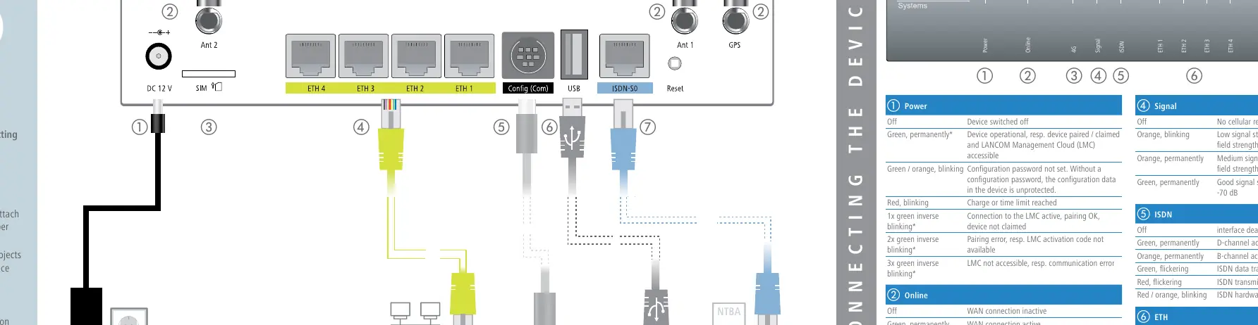
- Power: Connect the power adapter. Turn the bayonet connector 90° clockwise until it clicks into place. Use only the supplied power adapter.
- Antennas: Screw the two supplied cellular antennas onto the connectors labeled Ant 1 and Ant 2. Important: Antennas must only be attached or changed when the device is switched off to prevent damage to the 4G module.
- SIM Card: Slide the SIM card into the slot using the marker to ensure correct orientation. Ensure it clicks into place. Important: Insert or remove the SIM card only when the device is switched off.
- Ethernet: Use the cable with kiwi-colored connectors to connect interfaces ETH 1 to ETH 4 to your PC or LAN switch.
- Serial Interface: Connect to a PC using a configuration cable (available separately).
- USB Interface: Connect a USB printer or USB flash drive for device configuration.
- ISDN Interface: Use the light-blue connector cable to connect to the NTBA if using ISDN.
LED status indicators
The device features several LEDs to indicate operational status:
- Power: Green (operational), Red blinking (charge/time limit reached), Green/Orange blinking (password not set).
- Online: Green (WAN connection active), Red (WAN connection error).
- 4G: Green (connection active), Orange (logging on), Red (hardware error).
- Signal: Green (good signal), Orange (medium/low signal), Off (no reception).
- ISDN: Green (D-channel active), Orange (B-channel active), Red (transmission error).
- ETH: Green (connection operational), Flickering (data transmission).
- VPN: Green (VPN connection active).
Technical specifications
- Power supply: 12 V DC, max 12.5 W.
- Environment: 5 – 40 °C; 0 – 95 % humidity (non-condensing).
- Housing: 210 x 45 x 140 mm.
- Supported standards: LTE, HSPA+, HSxPA, UMTS, EDGE, GPRS.
- Interfaces: 4x Gigabit Ethernet, USB 2.0, ISDN-S0, Serial, 2x SMA (Antennas), 1x GPS.
Manufacturer information
LANCOM Systems GmbH
Practical help
Common problems
Device not connecting to cellular network
Check SIM card insertion and signal strength (Signal LED). Ensure SIM was inserted while the device was powered off.
Configuration password not set
The Power LED will blink green/orange. The device configuration data is currently unprotected.
ISDN transmission error
Check the ISDN LED; if it is flickering red, there is an ISDN transmission error. If it is red/orange blinking, there is an ISDN hardware error.
Before use
- Attach adhesive rubber footpads for desktop operation.
- Ensure ventilation slots are clear of obstructions.
- Use only the supplied power adapter (12 V DC).
- Ensure the device is switched off before attaching/removing antennas.
- Ensure the device is switched off before inserting/removing the SIM card.
Specs in practice
- Power consumption
- Maximum 12.5 W.
- Ethernet ports
- 4x 10/100/1000 Mbps ports; default set to switch mode, can be configured as WAN ports.
Images and diagrams
- The device has 7 primary connection points: 1. Power, 2. Antennas (Ant 1/Ant 2), 3. SIM card slot, 4. Ethernet ports (ETH 1-4), 5. Serial interface, 6. USB interface, 7. ISDN interface.
Model compatibility
- Supports LTE, HSPA+, HSxPA, UMTS, EDGE, GPRS.
- Ethernet ports support IEEE 802.3az energy-efficient features.

Manual page author
Emily Carter
User documentation editor
Prepares concise manual descriptions and highlights the most useful setup, operation, and maintenance information for readers.