Electronics / Routers
Quick Reference Guide for LANCOM 1793VAW Business VPN Router
Quick reference guide for the LANCOM 1793VAW Business VPN Router. Includes port layout, LED status indicators, mounting instructions, and technical specifications.
Quick answers from the manual
Quick answer
- The LANCOM 1793VAW is a business VPN router. Setup involves connecting the VDSL/ADSL line, Ethernet devices, and power. Status is monitored via front-panel LEDs. p. 1
Key actions
- Connect Power p. 1
- Reset Device p. 1
First start
- Initial Setup p. 1
Problems and fixes
DSL hardware error
Check DSL LED; Red/orange blinking indicates hardware error.
p. 1Maintenance and reset
- Resetting the device p. 1
Technical specifications
| Parameter | Value | Meaning | Pages |
|---|---|---|---|
| Power Supply | 12 V DC | External power adapter (230 V) | p. 1 |
| Dimensions | 210 x 45 x 140 mm | Width x Height x Depth | p. 1 |
Where to find it in the PDF
- Quick Reference Guide p. 1
Table of contents
Manual images
Click an image to enlargeQuick Guide for LANCOM 1793VAW
This guide provides essential information for setting up and operating the LANCOM 1793VAW Business VPN Router. Before initial startup, ensure the device is placed in a well-ventilated area and connected to a professionally installed power supply.
Device Setup and Connections
The device features various ports on the rear panel for network and peripheral connectivity:

- VDSL / ADSL Interface: Use the supplied DSL cable to connect to your provider's telephone socket.
- Ethernet Interfaces (ETH 1-4): Use the kiwi-colored cable to connect PCs or LAN switches. These ports are Gigabit Ethernet (10/100/1000 Mbps).
- Analog Interfaces: Connect analog terminal devices directly via RJ11 or using the enclosed TAE/RJ11 adapters.
- ISDN Interfaces: Supports internal (NT) or external (TE) ISDN bus.
- USB Interface: Connect USB printers or memory sticks.
- Power: Connect the supplied power adapter and turn the bayonet connector 90° clockwise until it clicks.
Mounting Instructions
- Desktop: Attach the adhesive rubber footpads to the bottom of the device.
- Wall Mounting: Use the provided drilling template.
- Rack Mounting: Use the optional LANCOM Rack Mount (sold separately).
- Ventilation: Keep the ventilation slots on the side of the device clear of obstruction. Do not place objects on top of the device.
LED Status Indicators
The device uses various LEDs to indicate operational status:
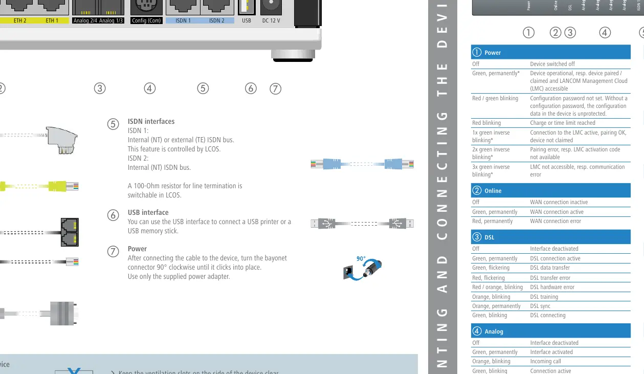
- Power: Green (operational), Red/Green blinking (password not set), Red blinking (charge/time limit reached).
- Online: Green (WAN connection active), Red (WAN connection error).
- DSL: Green (connection active), Orange (sync/training), Red (hardware error).
- ETH: Green (connection operational), Flickering (data transmission).
- VPN: Green (connection active), Flashing (connecting).
- Reset: Use a paper clip for a short press (restart) or long press (reset).
Technical Specifications
- Power Supply: 12 V DC, external adapter (230 V).
- Power Consumption: Max. ca. 17 W.
- Environment: 0–40 °C; 0–95 % humidity (non-condensing).
- Housing: Robust synthetic housing, wall-mountable, Kensington lock.
- Interfaces: VDSL2/ADSL2+, 4x Gigabit Ethernet, 2x ISDN, 4x Analog, 1x USB, Serial Config (COM).
Manufacturer information
LANCOM Systems GmbH
Practical help
Common problems
Power LED is red/green blinking
The configuration password has not been set. The device configuration is currently unprotected.
DSL LED is orange blinking
The device is currently in DSL training mode.
Online LED is red
There is a WAN connection error.
VPN LED is off
The VPN connection is inactive.
Before use
- Ensure ventilation slots on the side are clear.
- Attach adhesive rubber footpads if placing on a desktop.
- Use the drilling template for wall mounting.
- Use only the supplied power adapter.
- Secure the power cable by turning the bayonet connector 90° clockwise.
Images and diagrams
- The rear panel contains the VDSL/ADSL port, 4 Ethernet ports, 4 Analog ports, 2 ISDN ports, USB port, and the DC 12V power input.
- The bayonet connector for power requires a 90-degree turn to lock.
Model compatibility
- Compatible with Deutsche Telekom VDSL2 and U-R2 (1TR112).
- Supports ADSL2+ over ISDN and POTS.

Manual page author
Emily Carter
User documentation editor
Prepares concise manual descriptions and highlights the most useful setup, operation, and maintenance information for readers.