Electronics / Routers
Hardware Quick Reference for LANCOM 1790-4G+ Router
Quick setup guide for the LANCOM 1790-4G+ router. Includes hardware connection instructions, SIM card installation, LED status indicators, and technical specifications.
Quick answers from the manual
Quick answer
- The LANCOM 1790-4G+ is a high-performance mobile VPN router. To set it up, connect the cellular antennas, WAN cable, and power adapter. Insert the SIM card into the bottom slot if using cellular connectivity. p. 1
Key actions
- Connect antennas p. 1
- Insert SIM card p. 1
- Connect power p. 1
First start
- Connect antennas, WAN, and Ethernet cables, insert SIM card, and connect power adapter. p. 1
Problems and fixes
Device reset
Short press the Reset button to restart; long press to reset.
p. 1Maintenance and reset
- Use the Reset button (operated with a paper clip) for restart or reset. p. 1
Technical specifications
| Parameter | Value | Meaning | Pages |
|---|---|---|---|
| Power supply | 12 V DC | External power adapter with bayonet connector | p. 1 |
| Power consumption | Max. 9 W | Maximum power draw | p. 1 |
Where to find it in the PDF
- Hardware Quick Reference p. 1
Table of contents
Manual images
Click an image to enlargeQuick guide from the manual
The LANCOM 1790-4G+ is a high-performance mobile VPN router. This guide provides essential information for hardware installation, including antenna connection, SIM card insertion, and port configuration. Ensure the device is operated with a professionally installed power supply and that ventilation slots remain clear at all times.
Installation and Connection
- LTE / 4G Antennas: Connect the two supplied cellular antennas to the connectors labeled Ant 1 and Ant 2.
- WAN Interface: Connect your WAN modem to the WAN interface using the provided Ethernet cable with dark green connectors.
- Ethernet Interfaces: Use the cable with green-colored connectors to connect one of the ETH 1 to ETH 3 interfaces to your PC or LAN switch.
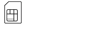
- SIM Card Slot: Located on the bottom of the device. Release the SIM-card holder, lever it upwards, slide the SIM card into the guide slot, and press the holder down until it clicks into place.
- Configuration Interface: Use the serial interface for configuration (requires an optional serial configuration cable).
- USB Interface: Connect a USB printer or USB memory stick as needed.
- Power: Connect the power cable and turn the bayonet connector 90° clockwise until it clicks into place. Use only the supplied power adapter.
Setup Notes
- The power plug must be freely accessible at all times.
- For desktop operation, attach the adhesive rubber footpads.
- Do not place objects on top of the device.
- Keep all ventilation slots clear of obstruction.
- For wall mounting, use the supplied drilling template.
- Rack installation is possible with the optional LANCOM Rack Mount.
LED Status Indicators
The device features several LEDs to indicate status:
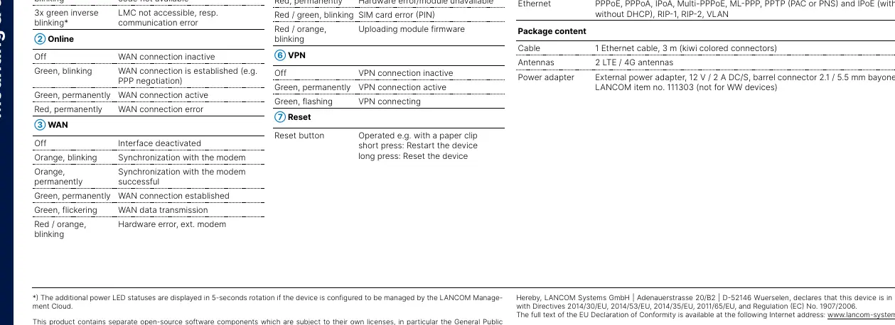
- Power: Indicates device operation and LMC (LANCOM Management Cloud) status.
- Online: Shows WAN connection status.
- WAN: Indicates synchronization and data transmission status.
- ETH: Shows network device connection and data traffic.
- 4G: Indicates cellular interface status, logon, and hardware errors.
- VPN: Shows VPN connection status.
- Reset: Use a paper clip for a short press to restart or a long press to reset the device.
Technical Specifications
- Power Supply: 12 V DC, external adapter (230 V) with bayonet connector.
- Power Consumption: Max. 9 W.
- Environment: Temperature 0–40 °C; humidity 0–95% (non-condensing).
- Interfaces: 4G (Ant 1, Ant 2), WAN (Gigabit Ethernet), 3x ETH (Gigabit Ethernet), USB 2.0, Serial Config (V.24).
- Housing: Robust synthetic housing, wall-mountable, Kensington lock.
Manufacturer information
LANCOM Systems GmbH
Practical help
Common problems
4G LED is permanently red
Indicates a hardware error or the module is unavailable.
Power LED is blinking red/green
Configuration password is not set; the device data is currently unprotected.
WAN LED is permanently red
Indicates a WAN connection error.
Device not connecting to LMC
Check for 3x green inverse blinking on the Power LED, which indicates an LMC communication error.
Before use
- Ensure the power plug is freely accessible.
- Attach adhesive rubber footpads if using on a desktop.
- Keep ventilation slots clear of obstruction.
- Use only the supplied power adapter.
- Ensure the SIM card is correctly inserted into the bottom slot.
Specs in practice
- Power Consumption
- Maximum 9 W; ensure the power source can handle this load.
Images and diagrams
- Ant 1/2: Connect cellular antennas here.
- WAN: Connect your internet modem here.
- ETH 1-3: Connect local network devices here.
- SIM Slot: Located on the bottom of the unit.
Model compatibility
- Supports LANCOM AirLancer antennas for 4G/3G.
- USB port supports USB printers, serial devices, or USB drives (FAT file system).

Manual page author
Emily Carter
User documentation editor
Prepares concise manual descriptions and highlights the most useful setup, operation, and maintenance information for readers.