Electronics / Routers
LANCOM 1790VA-4G Router Quick Reference Guide
Quick reference guide for the LANCOM 1790VA-4G router. Includes installation steps, antenna setup, LED status indicators, hardware specifications, and connection instructions.
Quick answers from the manual
Quick answer
- The LANCOM 1790VA-4G is a VDSL/4G router. To set it up, connect the antennas, DSL/Ethernet cables, and power adapter. Use the LED indicators on the front panel to monitor the connection status. p. 1
Key actions
- Connect LTE/4G antennas p. 1
- Connect power p. 1
- Insert SIM card p. 1
First start
- Ensure the device is placed on a flat surface or wall-mounted with clear ventilation before connecting power. p. 1
Problems and fixes
Red Power LED
Configuration password not set or charge/time limit reached.
p. 1
Red DSL LED
DSL hardware error.
p. 1Maintenance and reset
- Use a paper clip to press the reset button. A short press restarts the device; a long press resets it. p. 1
Technical specifications
| Parameter | Value | Meaning | Pages |
|---|---|---|---|
| Power supply | 12 V DC | External power adapter (230 V) | p. 1 |
| Dimensions | 210 x 45 x 140 mm | Width x Height x Depth | p. 1 |
Where to find it in the PDF
- Quick Reference Guide p. 1
Table of contents
Manual images
Click an image to enlargeQuick guide from the manual
The LANCOM 1790VA-4G is a high-performance router designed for VDSL and 4G connectivity. This guide provides essential instructions for mounting, connecting, and interpreting the device status indicators.
Mounting and connecting the device
Follow these steps to set up your router:
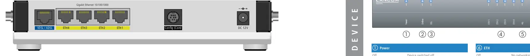
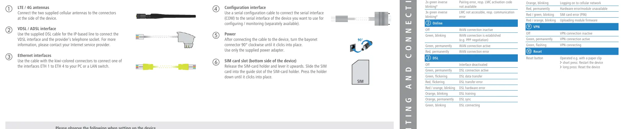
- LTE / 4G Antennas: Connect the two supplied cellular antennas to the connectors located on the side of the device.
- VDSL / ADSL Interface: Use the supplied DSL cable to connect the VDSL interface to your provider's telephone socket.
- Ethernet Interfaces: Use the kiwi-colored cable to connect one of the ETH 1 to ETH 4 ports to your PC or LAN switch.
- Configuration Interface: Use a serial configuration cable (not supplied) to connect the COM port for monitoring or configuration.
- Power: Connect the power adapter. Turn the bayonet connector 90° clockwise until it clicks into place. Use only the supplied power adapter.
- SIM Card Slot: Located on the bottom of the device. Release the SIM-card holder, slide the SIM card into the guide slot, and press the holder down until it clicks.
LED status indicators
The device features several LEDs to indicate operational status:
- Power: Green indicates the device is operational. Red/green blinking indicates a configuration password is not set.
- Online: Green blinking indicates WAN connection establishment; green permanently indicates an active WAN connection.
- DSL: Green indicates an active DSL connection; red indicates a DSL hardware error.
- ETH: Green indicates a connection to a network device.
- 4G: Green indicates an active cellular connection; orange indicates successful logon; red indicates a hardware error or SIM card error.
- VPN: Green indicates an active VPN connection.
Resetting the device
The reset button is located on the device. Use a paper clip to operate it:
- Short press: Restarts the device.
- Long press: Resets the device to factory settings.
Technical specifications
- Power supply: 12 V DC, max 18 W.
- Interfaces: VDSL2 (profiles 8a-35b), 4x Gigabit Ethernet, 4G (SMA connectors).
- Environment: 0–40 °C, 0–95 % humidity (non-condensing).
- Dimensions: 210 x 45 x 140 mm.
Safety and usage notes
- Do not place objects on top of the device.
- Attach adhesive rubber footpads if operating on a desktop.
- Use the supplied drilling template for wall mounting.
- Ensure ventilation slots on the side remain clear.
Manufacturer information
LANCOM Systems GmbH
Practical help
Common problems
Device does not power on
Ensure the power adapter is connected and the bayonet connector is turned 90° clockwise until it clicks.
No WAN connection
Check the DSL cable connection to the provider's telephone socket and verify provider settings.
SIM card error (Red/green blinking 4G LED)
Check that the SIM card is correctly inserted into the holder on the bottom of the device.
Before use
- Ensure the power supply is 12V DC.
- Attach adhesive rubber footpads for desktop operation.
- Use the drilling template for wall mounting.
- Keep ventilation slots on the side of the device clear.
- Ensure the device is operated with a professionally installed power supply.
Images and diagrams
- The front panel contains ports for VDSL/ADSL, ETH1-4, Config, and DC 12V power.
- The SIM card slot is located on the bottom of the device.
- The bayonet connector requires a 90-degree turn to lock securely.
Model compatibility
- Compatible with VDSL2 from Deutsche Telekom.
- Supports optional LANCOM Rack Mount (separately available).

Manual page author
David Miller
Documentation analyst
Organizes user manual content into clear summaries, with attention to model details, product context, and everyday usability.