Tools / Woodworking Tools
User Manual for Logosol Loncin 15HP Gasoline Engine
Quick guide for the Logosol Loncin 15HP gasoline engine. Includes installation steps, throttle cable assembly, battery wiring, and safety switch connection instructions.
Table of contents
Manual images
Click an image to enlargeQuick guide from the manual
This manual provides essential installation and assembly instructions for the Logosol Loncin 15HP gasoline engine. It covers the mechanical mounting of the engine, throttle cable setup, electrical wiring for the battery, and the installation of the safety switch. Always read the safety instructions before operating the equipment to prevent serious injury.
Installation and Assembly
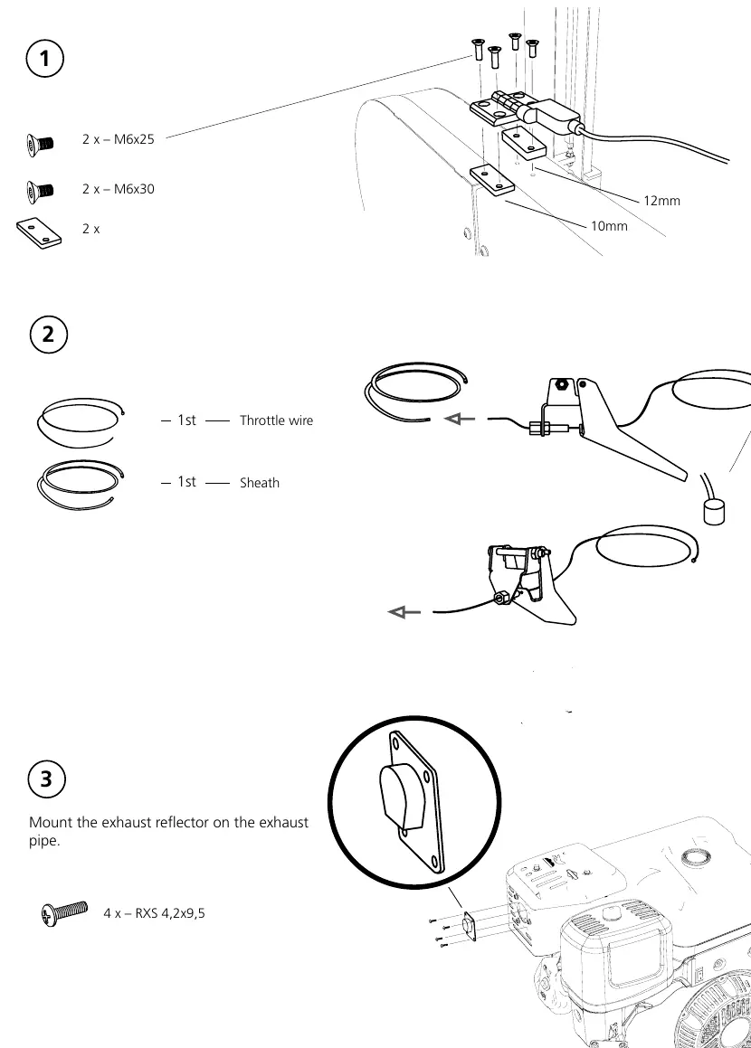
- Mounting: Secure the engine using the provided M6x25 and M6x30 bolts.
- Throttle Setup: Install the throttle wire and sheath.
- Exhaust: Mount the exhaust reflector onto the exhaust pipe using 4 x RXS 4,2x9,5 screws.
- Engine Mounting: Secure the engine to the chassis using 4 x M10x40 bolts, nuts, and washers.
- Pulley Assembly: Install the pulley components as shown in the diagram using the specified U6S 3/8-24 x2 bolt and SRKB 12,5x35x2 washer.
- Airbox: Remove the airbox filter and the lower part of the airbox to access the throttle assembly area.
- Throttle Cable: Attach the throttle cable to the bracket and the throttle control. Untighten the nut holding the throttle control and verify that the throttle returns easily.
Wiring and Electrical Connections
Proper electrical connection is critical for engine operation and safety.
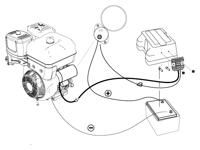
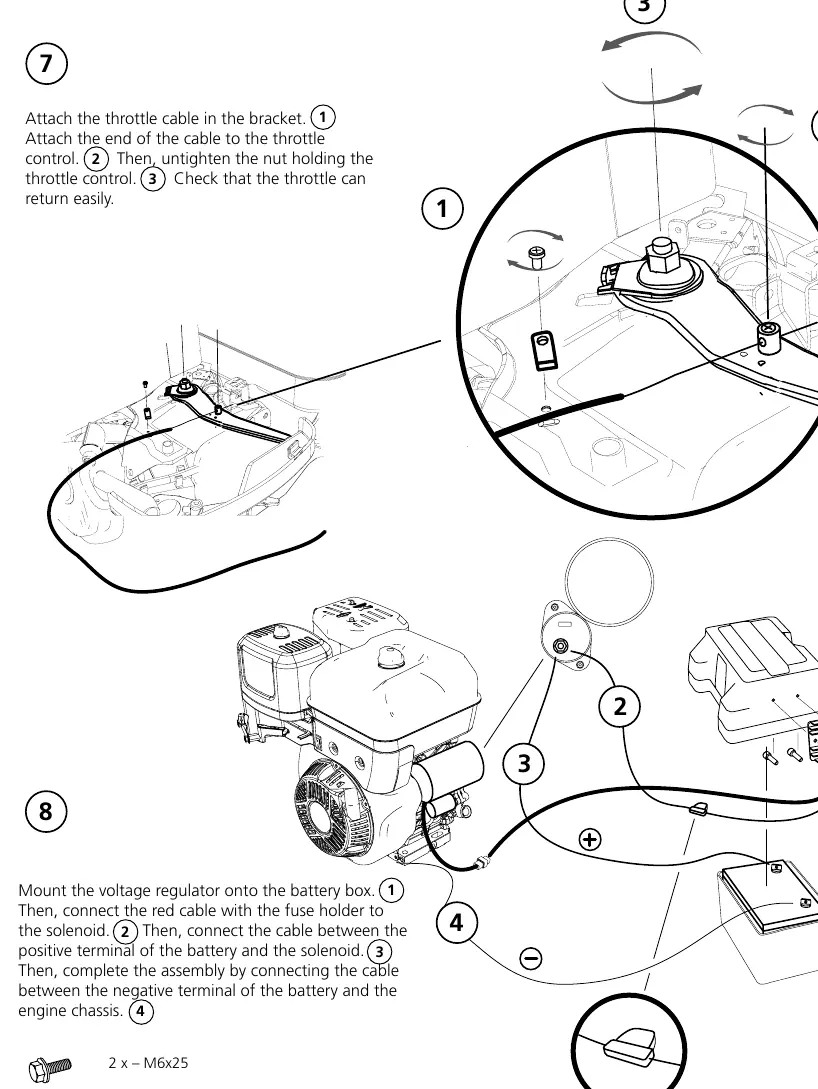
- Voltage Regulator and Battery: Mount the voltage regulator onto the battery box. Connect the red cable with the fuse holder to the solenoid. Connect the positive terminal of the battery to the solenoid. Finally, connect the negative terminal of the battery to the engine chassis.
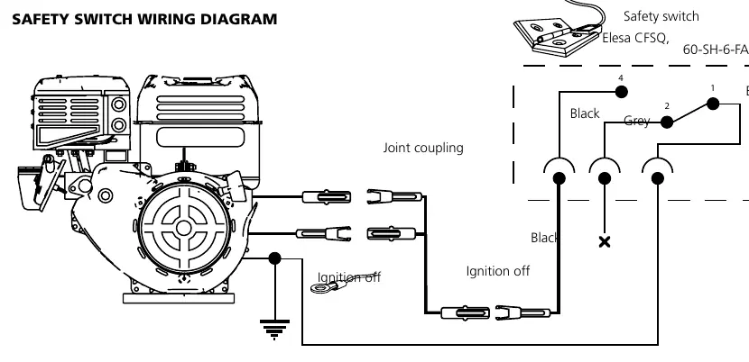
- Safety Switch: Connect the safety switch to the divisible connector in the cable kit. Couple the joint piece and connect the switch. Couple the ring cable lug to the motor chassis. Refer to the safety switch wiring diagram for specific color-coded connections (Black, Grey, Blue).
Practical help
Common problems
Throttle does not return smoothly
Check the throttle cable attachment and ensure the nut holding the throttle control is not overtightened.
Engine fails to start or ignition issues
Verify all electrical connections, specifically the safety switch coupling and the battery terminal connections.
Before use
- Ensure all mounting bolts (M6 and M10) are tightened to specifications.
- Verify the throttle cable moves freely without obstruction.
- Confirm the exhaust reflector is securely mounted.
- Check that the battery positive cable is connected to the solenoid and the negative to the chassis.
- Ensure the safety switch is properly coupled to the cable kit.
Images and diagrams
- The wiring diagram illustrates the connection path for the safety switch (Elesa CFSQ) and the ignition off circuit.
- Assembly diagrams detail the sequence for mounting the engine and throttle components.
Model compatibility
- This engine is designed for integration with Logosol machinery.

Manual page author
David Miller
Documentation analyst
Organizes user manual content into clear summaries, with attention to model details, product context, and everyday usability.