Tools / Woodworking Tools
User Manual for Logosol Pro Feed 12V
Comprehensive user manual for the Logosol Pro Feed 12V sawmill feed unit. This guide provides detailed assembly instructions, wiring diagrams, control panel operation, safety guidelines, and troubleshooting procedures to ensure safe and...
Table of contents
Manual images
Click an image to enlargeQuick Guide
The Logosol Pro Feed 12V is a feed unit designed for band sawmills. Before operating, ensure you have read the safety instructions, verified the power supply, and confirmed that the chain is correctly aligned between the gears. Always ensure the safety guards are closed, as the machine is equipped with an interlock safety switch.
Safety Instructions
WARNING: Incorrect use can result in serious or fatal injuries. Always wear approved personal protective equipment, including hearing protection, safety goggles, protective footwear with steel toe-caps, and full-length protective trousers. Use protective gloves when handling band blades.
- Worksite: Operate in full daylight or adequate lighting. Keep the area free from clutter, pets, and children. Ensure the ground is level and hardpacked.
- Safety Equipment: Never use the machine if safety equipment is defective. The interlock safety switch on the band wheel guard prevents operation if guards are open.
- Operator: Persons under 18 may not operate the machine. Do not operate if tired, under the influence of alcohol, or medication that impairs reaction times.
Assembly
The assembly process involves multiple steps, including mounting the feed unit to the sawmill rail, installing the control panel, and setting up the drive chain. Use the provided fasteners (bolts and nuts) as specified in the manual. Ensure all joints are tightened appropriately. When the lubrication symbol appears, apply universal grease to the parts before installation.
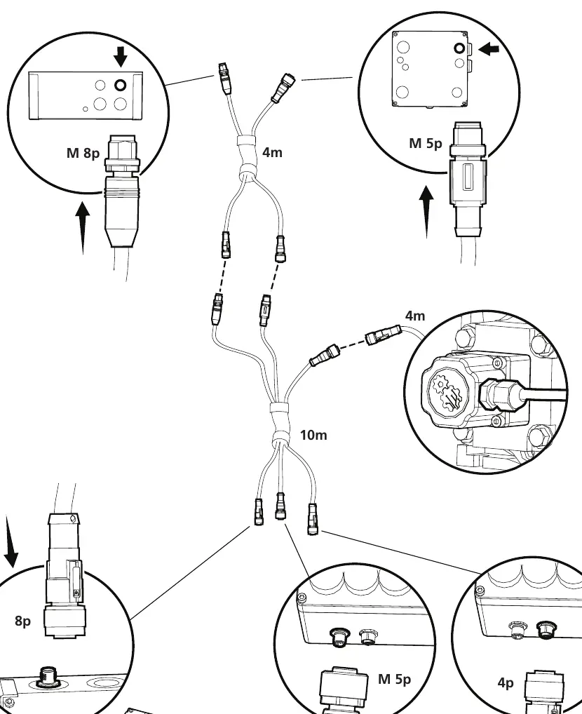
Connection of Cable Trunks
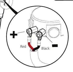
Proper wiring is essential for the feed unit to function. Connect the cable trunks according to the diagrams provided in the manual. Ensure the red and black cables are connected to the correct poles on the motor and battery. Verify that the cable trunk and supply cable are suspended in the strain relief to prevent damage during operation.
At First Startup
Before the first run, perform the following checks:
- Ensure the power supply is working.
- Run the saw head along the rail using the actuator.
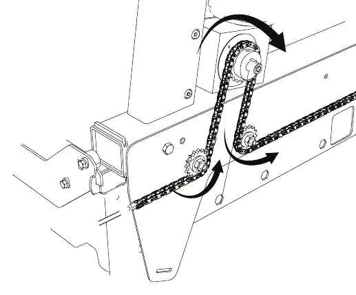
- Listen for abnormal noise and ensure the chain is aligned between the gears.
- Check that no physical collision occurs along the length of the rail.
- Verify that both the cable trunk and supply cable are suspended in the strain relief.
Control Panel
The control panel features the following elements:

- Operating lever: Controls the movement of the saw head.
- Start saw motor: Operated in combination with the safety switch.
- Safety switch: Must be engaged for operation.
- Feed speed: Dial to adjust the speed of the feed (0-100).
Troubleshooting
If you encounter issues, refer to the following:
- Machine does not start: Check for loose contacts, moisture, tripped RCD, or blown fuses.
- Abnormal noises: Check for poor chain alignment, insufficient or over-tensioned chain, or worn bearings/gearbox.
- Wrong direction: Phase reversed; swap the cables on the motor poles.
- Engine does not run: Motor may be overheating; wait for it to cool down.
Practical help
Common problems
Machine does not start
Check for loose contacts, moisture, tripped RCD, or blown fuses in the saw box. Try removing and reinstalling connectors.
Abnormal noises from mechanism
Check alignment between lower and upper lift sprockets, chain tension, and inspect bearings/gearbox for wear.
Machine runs in wrong direction
Phase reversed due to incorrect motor pole connection; swap the cables on the motor poles.
Engine does not run
Motor protection may have tripped due to overheating. Wait until the motor has cooled and resume operation.
Before use
- Check that the power supply is working.
- Ensure the chain is aligned between the gears.
- Check for physical collisions along the length of the rail.
- Verify that the cable trunk and supply cable are suspended in the strain relief.
- Ensure all safety guards are closed.
Specs in practice
- ABC type fire extinguisher
- Recommended minimum 6 kg fire extinguisher to keep at the worksite.
Images and diagrams
- Control panel: Includes operating lever, start button, safety switch, and feed speed dial.
- Wiring: Red and black cables must be connected to the correct positive and negative terminals.
Model compatibility
- Motormodel might vary; refer to your specific motor manual for connection details.

Manual page author
David Miller
Documentation analyst
Organizes user manual content into clear summaries, with attention to model details, product context, and everyday usability.