Industrial / Process Sensors
User Manual for Microsonic pico+ Ultrasonic Sensor
Quick guide for the Microsonic pico+ ultrasonic sensor. Learn about installation, Teach-in parameter setup, synchronization, and technical specifications for the pico+15, 25, 35, and 100 series.
Table of contents
Manual images
Click an image to enlargeQuick guide from the manual
The pico+ ultrasonic sensor is designed for non-contact distance measurement. Key operations include setting window limits and output characteristics via the Teach-in procedure. Ensure the sensor is installed by qualified staff and note that it is not a safety component for personal or machine protection.
Product description
The sensor measures distance to objects within its detection zone, outputting a distance-proportional analogue signal. The transducer surface is laminated with PTFE film and sealed against the housing, allowing for measurement in up to 0.5 bar overpressure. Two LEDs indicate operation and the state of the analogue output.
Installation and wiring
Mount the sensor at the desired location. For the pico+100/TF model, avoid using the first 5 mm of the M22 thread on the transducer side for mounting. Connect the cable to the M12 device plug using the following pin assignment:
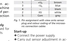
- Pin 1: +UB (brown)
- Pin 3: -UB (blue)
- Pin 4: Output (black)
- Pin 2: I/U (white)
- Pin 5: Com (grey)
Teach-in procedure
The sensor parameters are set via the Teach-in procedure using the Com input:
- Set window limits: Place object at position 1, connect Com to +UB for 3s until both LEDs flash simultaneously. Place object at position 2, connect Com to +UB for 1s.
- Set rising/falling output characteristic: Connect Com to +UB for 13s until both LEDs flash alternately. Connect Com to +UB for 1s to toggle between rising and falling curves.
Synchronization
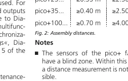
If the assembly distance is below the values specified in the manual (Fig. 2), internal synchronization is required. First, set the switched outputs of all sensors. Then, set the multifunctional output »Com« to »synchronization« and connect pin 5 of all sensors together.
Maintenance
The sensors are maintenance-free. If the sensor surface becomes dirty, clean it carefully. The sensor automatically detects its operating temperature upon power-up and applies compensation after 120 seconds.
Technical data
The pico+ series includes models with varying ranges (15, 25, 35, 100). All models feature IP 67 protection, 5-pin M12 initiator plug, and operate between -25 to +70 °C. Detailed range, blind zone, and frequency specifications are provided in the technical data section of the manual.
Practical help
Common problems
Sensor does not detect object
Ensure the object is outside the blind zone (e.g., 20mm for pico+15, 120mm for pico+100) and within the operating range.
Teach-in procedure not working
Check if synchronization is activated, as this disables the Teach-in function. Ensure the power supply is stable.
Inaccurate measurements
Verify that the sensor is properly aligned with the object. Ensure the object is within the detection zone; reflections outside this area cannot be evaluated.
Before use
- Verify power supply voltage (10-30V DC).
- Ensure installation is performed by qualified staff.
- Check that the object is outside the sensor's blind zone.
- Confirm wiring matches the M12 pin assignment (Fig 1).
- Clean the sensor surface if necessary.
Specs in practice
- Operating range
- The distance range where the sensor reliably detects objects.
- Analogue output
- A signal (4-20mA or 0-10V) proportional to the measured distance.
Images and diagrams
- Fig 1: Pin assignment for the M12 plug, showing the color coding for the 5-pin connection.
- Fig 2: Assembly distances required to avoid interference between sensors.
- Diagram 1: Flowchart for the Teach-in procedure to set window limits and output characteristics.
Model compatibility
- Not suitable for personal or machine protection (not a safety component).
- Compatible with LinkControl adapter and software for advanced parameter settings.
- Supports internal synchronization for up to 10 sensors.

Manual page author
David Miller
Documentation analyst
Organizes user manual content into clear summaries, with attention to model details, product context, and everyday usability.