Industrial / Process Sensors
User Manual for Microsonic lpc+ Ultrasonic Sensor
Quick guide for the Microsonic lpc+ ultrasonic sensor. Learn about installation, Teach-in parameter settings, IO-Link configuration, operating modes, and technical specifications.
Table of contents
Manual images
Click an image to enlargeQuick guide from the manual
The lpc+ ultrasonic sensor is configured primarily via the Teach-in procedure. To set parameters, you must connect the Com pin (pin 5) to either +UB or -UB for specific durations as detailed in the Teach-in diagram. The sensor features two push-pull switching outputs and supports IO-Link V1.1. If a Teach-in process is not completed, changes are discarded after approximately 4 minutes.
Product description
The lpc+ sensor provides non-contact distance measurement. It features four LEDs to indicate the state of the switching outputs. The sensor is IO-Link capable and supports the Smart Sensor Profile. It is equipped with internal temperature compensation, which reaches its optimal working point after approximately 120 seconds of operation.
Installation
- Mount the sensor at the desired location.
- Connect a connection cable to the M12 device plug.
- Ensure installation is performed by qualified staff only.
- Note that the sensor has a blind zone where distance measurement is not possible.
Operating modes
The sensor supports three operating modes for the switching output:
- Operation with one switching point: The output is set when the object falls below the set switching point.
- Window mode: The output is set when the object is outside the defined window limits.
- Two-way reflective barrier: The output is set when the object is between the sensor and a fixed reflector.
Synchronisation
If multiple sensors are installed close together, internal synchronisation should be used to prevent interference. This requires enabling the »Teach-in + sync« function and interconnecting pin 5 of all sensors to be synchronised.
Maintenance
Microsonic sensors are maintenance-free. In case of excess caked-on dirt, it is recommended to clean the white sensor surface.
Technical data
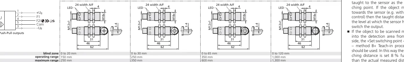
The lpc+ family includes models with varying ranges (150 mm to 1,000 mm). All models operate on 10 to 30 V DC and feature reverse polarity protection. The housing consists of a nickel-plated brass sleeve with PBT plastic parts and a polyurethane foam transducer.
Practical help
Common problems
Sensor not switching
Ensure the object is within the detection zone and the Teach-in procedure was successfully completed.
Teach-in process fails
Ensure the Com pin is connected to the correct voltage (+UB or -UB) for the exact required duration.
Sensor interference
If multiple sensors are used, enable synchronisation and interconnect pin 5 of all sensors.
Before use
- Verify power supply is 10-30V DC.
- Ensure installation is performed by qualified staff.
- Check that the object is outside the sensor's blind zone.
- Connect the M12 cable according to the pin assignment (Pin 1: +UB, Pin 2: F1, Pin 3: -UB, Pin 4: F2, Pin 5: Com).
- Allow 120 seconds for temperature compensation to reach the optimal working point.
Specs in practice
- Operating range
- The distance range where the sensor reliably detects objects.
- Switching hysteresis
- The distance difference between the switch-on and switch-off points.
Images and diagrams
- Diagram 1: Detailed flowchart for setting sensor parameters via the Teach-in procedure.
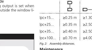
- Diagram 2: Minimum assembly distances for multiple sensors to avoid interference.
- Diagram 3: Visual guide for setting switching points based on object movement direction.
Model compatibility
- IO-Link V1.1 compliant.
- Requires 5-pin M12 circular plug.
- Compatible with LinkControl software for Windows.

Manual page author
David Miller
Documentation analyst
Organizes user manual content into clear summaries, with attention to model details, product context, and everyday usability.