Industrial / Process Sensors
Quick Start Guide for Rosemount 1208C Level and Flow Transmitter
Quick start guide for the Rosemount 1208C Level and Flow Transmitter. Includes installation instructions, electrical connection diagrams, power-up procedures, and configuration steps.
Table of contents
Manual images
Click an image to enlargeQuick Start Information
This guide provides essential instructions for the installation and setup of the Rosemount 1208C Level and Flow Transmitter. It is intended for qualified personnel only. Always refer to the full Reference Manual for detailed operational instructions and safety compliance.

Installing on a Tank
The transmitter can be mounted using a flange or an NPT threaded adapter. Ensure all safety precautions are followed, including disconnecting power before servicing.

Flange Mounting
- Place a suitable gasket on the tank flange.
- Position the flange over the gasket.
- Tighten the bolts and nuts with sufficient torque.
- Apply thread sealant to the transmitter threads (only for NPT threaded tank connections).
- Install and hand-tighten the transmitter. Note that the gasket is required for the G threaded version only.
NPT Threaded Adapter Mounting
- Apply thread sealant to the outer threads of the adapter.
- Mount the threaded adapter onto the tank.
- Apply thread sealant to the transmitter threads.
- Install and hand-tighten the transmitter.
Electrical Connections
The transmitter uses an M12 male (A-coded) connector. Use 24-18 AWG (0.20-0.75 mm2) wire. Twisted pairs and shielded wiring are recommended for high EMI environments.
- Power Supply: 14-35 Vdc at the transmitter terminals.
- Internal Power Consumption: Less than 0.8 W in normal operation.
- Cable Shield Grounding: Must be continuously connected throughout the segment and connected to a good earth ground at the power supply end.
- Load Limitations: For HART communication, a minimum loop resistance of 250 Ohm is required.
Wiring Diagram
The M12 connector pin assignment is as follows:
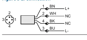
- Pin 1 (Brown): L+ (24 V)
- Pin 2 (White): NC (Not connected)
- Pin 3 (Blue): L- (0 V)
- Pin 4 (Black): NC (Not connected)
Power Up
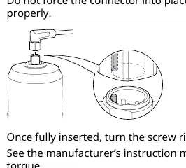
- Verify that the power supply is disconnected.
- Insert the M12 connector gently. Do not force it; ensure it is aligned properly.
- Once fully inserted, turn the screw ring until tight.
- Connect the power supply.
Configuration
The transmitter can be configured using FDI, DD, or DTM compliant systems.
- Software: Download the AMS Device Configurator at Emerson.com/AMSDeviceConfigurator.
- Drivers: Download the latest FDI/DD/DTM package at Emerson.com/DeviceInstallKits.
- Guided Setup: Navigate to Configure, then Guided Setup, then Initial Setup. Follow the on-screen instructions and use Verify Level to check measurements.
Official resources from the manual
Practical help
Common problems
Device not communicating
Verify that the correct FDI/DD/DTM package is loaded on your system.
Hot surfaces during service
The transmitter and process seal may be hot at high process temperatures; allow them to cool before servicing.
Connector insertion difficulty
Do not force the M12 connector. Check that it is aligned properly before inserting.
Before use
- Verify power supply is disconnected before installation.
- Ensure installation is performed by qualified personnel.
- Check that the correct gasket is used for the flange.
- Verify the power supply is 14-35 Vdc.
- Ensure cable shield is connected to earth ground at the power supply end.
Specs in practice
- Power Supply
- 14-35 Vdc at transmitter terminals.
- Loop Resistance
- Minimum 250 Ohm required for HART communication.
Images and diagrams
- Figure 3-2 shows the M12 connector pin assignment: Pin 1 (Brown) is L+, Pin 3 (Blue) is L-.
Model compatibility
- Requires AMS Device Configurator for configuration.
- Compatible with FDI, DD, and DTM compliant systems.

Manual page author
Emily Carter
User documentation editor
Prepares concise manual descriptions and highlights the most useful setup, operation, and maintenance information for readers.