Toys / Model Accessories
mxion RBM 4-Channel Track Occupancy Detector
Quick guide for the mxion RBM 4-channel track occupancy detector. Learn about installation, wiring, CV configuration, and system compatibility for S88, LocoNet, and XpressNet.
Table of contents
Manual images
Click an image to enlargeQuick guide from the manual
The mxion RBM is a 4-channel track occupancy detector designed for analog and digital model railway systems. It supports S88, LocoNet, and XpressNet bus systems. Key requirements for operation include ensuring no short circuits during installation, disconnecting bus cables before programming, and verifying that output voltages match your consumers.
Product description
The RBM module monitors 4 track sections and provides feedback. It features an integrated BM module, allowing for the monitoring of up to 8 sections if an additional BM module is connected. It supports train detection, switch control, and automated processes. The module is configured via CV programming.
Installation and wiring
Install the device in a protected location, ensuring it is not exposed to moisture. Ensure that mounting screws do not cause short circuits. Connect the track outputs, power supply, and bus systems according to the provided diagrams. The device is protected against shorts and excessive loads, but improper wiring can still cause damage.
Configuration and programming
Settings are made via DCC using a programming track or via POM (Programming on Main). Important: No bus cable must be plugged in during programming. For older control units, use registers 7 and 8. It is recommended to lock the module after successful programming using CV6 = 0.
Bus systems
- S88: No addressing or programming is required. Modules are connected in series. Use CV35 to set the pulse train offset if necessary.
- LocoNet: Addressing happens automatically. Configure the contact address or switch address based on the mode.
- XpressNet: Requires a unique address (CV1). Feedback and modes are specific to the command station used.
Technical data
- Voltage: 7-27V DC/DCC or 5-18V AC
- Current: 30mA (without functions)
- Max function current: 8A per channel (L1-L4)
- Temperature range: -20 to 80°C
- Dimensions: 9.3 x 7.7 x 2.5 cm
Practical help
Common problems
Programming not possible
Ensure no bus cable is plugged into the module during the programming process.
Wrong position in S88 system count
Adjust the S88 Reset-Counter (CV35) to match your system requirements (e.g., 16 for Digikeijs).
Device destroyed
Ensure output voltages are set to the appropriate value before connecting any other device.
Before use
- Verify that the power supply voltage is within 7-27V DC/DCC or 5-18V AC.
- Ensure the module is installed in a protected, dry location.
- Check that mounting screws do not create short circuits.
- Disconnect all bus cables before attempting to program the module.
- Ensure the device is programmed with the latest firmware if specific functions are required.
Specs in practice
- 7-27V DC/DCC
- Operating voltage range for the module.
- 8A per channel
- Maximum continuous current capacity for each of the 4 track sections.
Images and diagrams
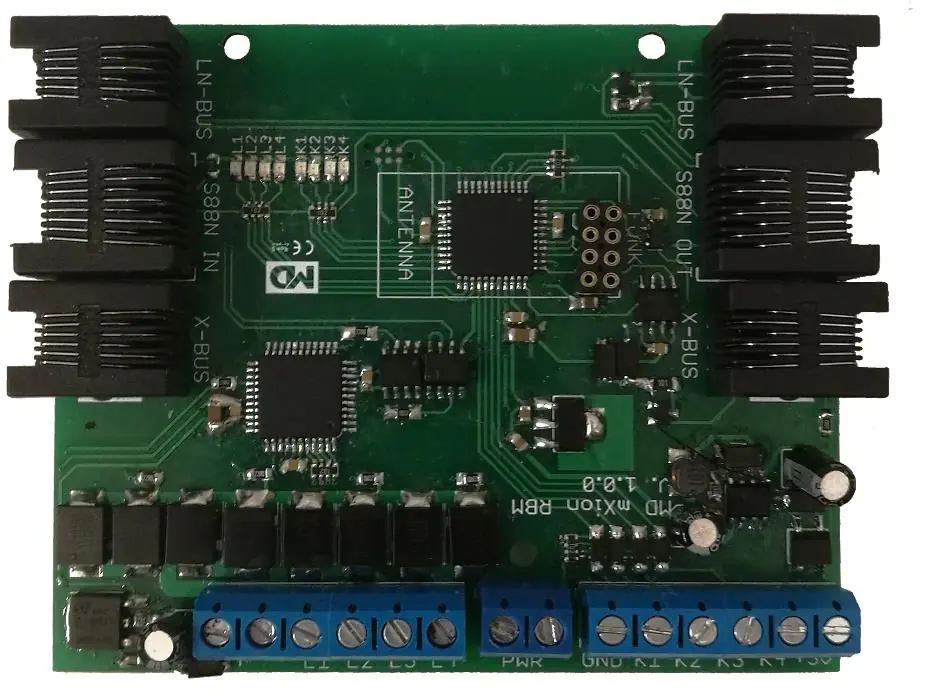
- The connector diagram identifies terminals for power supply, track outputs, ground, switch inputs, and bus connections (LocoNet, S88, XpressNet).
- The wiring diagram illustrates how to connect the RBM to the central unit/booster and track segments.
Model compatibility
- Compatible with S88, LocoNet, and XpressNet bus systems.
- Wireless feedback functionality requires an additional module.
- XpressNet feedback is only possible on specific command stations.

Manual page author
Michael Turner
Technical manual editor
Reviews PDF manuals for structure, safety notes, and practical product details so readers can find the right information quickly.