Health / Mobility Aids
User Manual for Ottobock 17BK1=* Multifunctional Corrective Orthotic Joint
Quick guide for the Ottobock 17BK1=* multifunctional corrective orthotic joint. Includes setup, adjustment, maintenance, and safety instructions.
Table of contents
Manual images
Click an image to enlargeQuick guide from the manual
The Ottobock 17BK1=* is a multifunctional corrective orthotic joint designed for orthotic fittings of upper or lower limbs. This document provides essential information for processing, installation, and maintenance. Always ensure the joint is aligned correctly and inspected semi-annually for wear and tear.
Product description
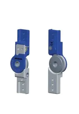
The system is available in four widths: 12 mm, 14 mm, 16 mm, and 20 mm. Key components include the upper joint section, gear wheel, joint nut, lower joint section, hollow screw, lock cover, and adjustment lever.
Intended use
The joint is intended exclusively for orthotic fittings of the hand, elbow, knee, or ankle. In a locked state, it must only be used in positioning orthoses that do not support body weight. It is contraindicated for structural joint contractures.
Safety instructions
- Mechanical damage: Use caution when working with the product. Discontinue use if functionality changes or is lost.
- Thermal overload: Do not perform heat treatment on the joint, as this damages bearing washers.
- Environmental conditions: Avoid storage in condensing humidity, contact with abrasive media (sand, dust), and temperatures outside the -10 °C to +40 °C range.
- Patient safety: Use only on one patient. Do not reach into the joint mechanism during daily use.
Processing and installation
The patient-specific plaster model must be fabricated first. Select the appropriate bars based on the size chart. Adapt the edges of the bars to the curves of the insertion zone for stability. Screw the bars to the orthotic joint and align the joint with the anatomical pivot point. When using two joints, ensure they are aligned parallel to one another. Glue the bars in the insertion zones using 636W28* special adhesive and allow to cure for at least 4 hours (final strength reached after 16 hours).
Adjustment
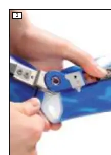
Do not perform angle adjustments on the patient under full load. Insert a hexagon wrench into the hollow screw of the lower joint section to set the desired angle. The adjustment lever indicates the functional state:
- Red: Joint is locked.
- Yellow: Joint is mobile in flexion, limited by the extension stop.
- Green: Joint is unlocked in flexion and extension.
Cleaning and maintenance
Clean the joint immediately after contact with saltwater, chlorinated/soapy water, or if it becomes dirty. Rinse with clean fresh water and allow to air dry. Avoid direct heat sources. The manufacturer recommends a semi-annual inspection for functionality and wear. Use only 633F7 special lubricant.
Manufacturer information
Ottobock SE & Co. KGaA
Practical help
Common problems
Joint movement loss
Check for thermal damage or debris; replace bearing washers if damaged.
Mechanical damage
Discontinue use and have the device checked by qualified personnel.
Excessive load
Shorten maintenance intervals based on expected patient load.
Before use
- Verify patient-specific plaster model is ready.
- Select appropriate bar size based on user height.
- Ensure parallel alignment of joints.
- Check fit and function before final delivery to the patient.
Specs in practice
- System width
- Available in 12mm, 14mm, 16mm, and 20mm.
Images and diagrams
- Fig 1: Components identification (1-12).
- Fig 2: Adjustment using hexagon wrench in the hollow screw.
- Fig 3-5: Color-coded functional states (Red, Yellow, Green).
Model compatibility
- Can be combined with 17BK2=* dynamic unit.
- 17BK1=* can be used with 17BK3=* medial support.

Manual page author
David Miller
Documentation analyst
Organizes user manual content into clear summaries, with attention to model details, product context, and everyday usability.