Automotive / Suspension Kits
Installation Manual for Pacbrake 10171-X Extreme Duty Air Suspension Kit
Comprehensive installation guide for the Pacbrake 10171-X Extreme Duty Air Suspension Kit for GMC/Chevrolet 2500 & 3500 trucks. Includes step-by-step assembly, mounting instructions, air line routing, and safety maintenance tips.
Table of contents
Manual images
Click an image to enlargeQuick guide from the manual
This manual provides instructions for installing the Pacbrake 10171-X Extreme Duty Air Suspension Kit on GMC/Chevrolet 2500 & 3500 trucks. The kit is designed to eliminate vehicle sag, sway, and bottoming out, with a load-leveling capacity of up to 7500 lbs. Before starting, ensure you have the correct kit for your vehicle's make, model, and year. The installation requires basic mechanical skills and specific tools, including a hoist or floor jack, torque wrench, and a nylon hose cutter.
Safety warnings
- Do not exceed GVWR: This kit does not increase the Gross Vehicle Weight Rating determined by the vehicle manufacturer.
- Clearance: The air bag must have clearance from surrounding components to prevent contact when inflated or compressed.
- Inflation safety: Never inflate an air spring unless it is secured to the vehicle.
- Pressure limits: Never operate the vehicle with less than 10 psi or more than 100 psi in the air springs.
Kit contents and tools
The kit includes extreme duty air bags, brackets, axle straps, hardware (bolts, nuts, washers), heat shield, and air line assembly. Required tools include a hoist or floor jack, safety stands, torque wrench, standard/metric sockets, 7/32" hex Allen wrench, 1-1/8" wrench, hose cutter, pipe thread sealant, and a spray bottle with dish soap/water for leak testing.
Installation procedure
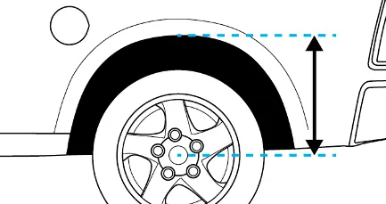
- Measure stock ride height: Park on a level surface, remove unnecessary weight, and measure the distance between the center of the wheel hub and the bottom of the fender well.
- Vehicle preparation: Raise the rear of the truck, place jack stands under the rear axle, and remove the rear wheels. Remove the jounce bumpers.
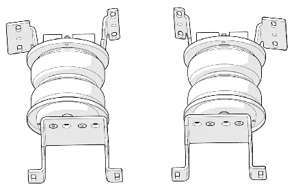
- Pre-assemble air springs: Install threaded fittings into the air springs. Attach roll plates and brackets to the air springs, securing them with countersunk screws torqued to 20 ft-lbs.
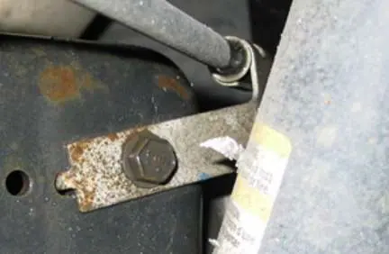
- Remove factory brackets: Remove the emergency brake cable bracket and brake line brackets as instructed for your specific vehicle side.
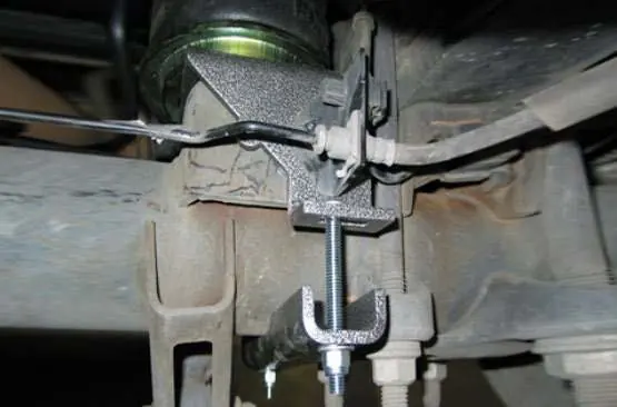
- Install air spring assemblies: Position the assembly on the jounce bumper stop. Secure the lower bracket with carriage bolts and axle straps.
- Mounting: Follow the specific instructions for your vehicle configuration (with or without 5th wheel hitch). Secure the upper bracket to the frame using U-bolts or self-threading bolts as required.
- Reattach brake lines: Reattach the brake line brackets to the lower brackets and torque to 12 ft-lbs.
- Install heat shield: Attach the heat shield to the exhaust pipe on the passenger side, ensuring 1/2" of dead space between the shield and the exhaust.
Air line installation and leak testing
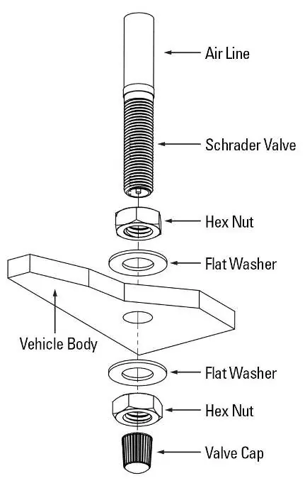
Cut the air line into two equal lengths using the provided hose cutter. Route the lines to the air spring fittings, moisten the ends, and push them into the fittings until they stop. Install the fill valves, typically in the license plate fastener locations. Inflate the springs to 90 psi and spray all connections with a mixture of dish soap and water. Bubbles indicate a leak; repair and retest until no leaks exist.
Operation and maintenance
Always maintain between 10 psi and 100 psi. Check air pressure daily for the first few days after installation. Re-torque all fasteners after the first 500 miles of driving. Do not use the air springs to lift the vehicle when unloaded, as this will result in a harsh ride.
Practical help
Common problems
Air leak at connection
Ensure the air line is cut squarely using the provided hose cutter; do not use scissors or wire cutters.
Air bag contact with components
Ensure proper clearance between the bag and surrounding parts; trim excess bolt length if necessary.
Harsh ride
Do not use air springs to lift the vehicle when unloaded; maintain at least 10 psi.
Before use
- Verify vehicle make, model, and year compatibility
- Ensure you have a hoist or floor jack and jack stands
- Check for rear wheel brake proportioning valve
- Have a nylon hose cutter or sharp utility knife ready
- Obtain thread sealant or Teflon tape
Images and diagrams
- Explosion diagram shows assembly order of brackets, air bag, and hardware.
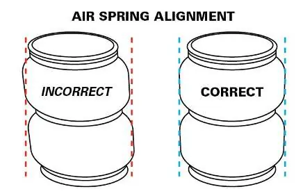
- Figure 9B illustrates correct vs. incorrect air spring alignment.
- Figure 13 shows the assembly of the inflation valve through the vehicle body.
Model compatibility
- Fits GMC/Chevrolet 2500 & 3500 2WD/4WD.
- Compatible with or without 5th wheel hitch (requires different installation steps).

Manual page author
Michael Turner
Technical manual editor
Reviews PDF manuals for structure, safety notes, and practical product details so readers can find the right information quickly.