Automotive / Suspension Kits
Installation Guide for Rough Country 110100D 6-Inch Lift Kit
Comprehensive installation guide for the Rough Country 110100D 6-inch lift kit for GM 2025 1500 trucks. Includes step-by-step front and rear suspension installation, torque specifications, and safety requirements.
Table of contents
Manual images
Click an image to enlargeQuick Guide
This installation guide is intended for the Rough Country 110100D 6-inch lift kit designed for GM 2025 1500 trucks. Rough Country strongly recommends that a certified technician perform the installation, as it requires professional knowledge of vehicle disassembly and reassembly procedures. Failure to follow these instructions may jeopardize vehicle safety.
Important Safety Warnings:
- The electric power steering must be unplugged before removing any steering components to prevent damage.
- Trucks with a mass damper on the front differential require the damper to be removed.
- Always wear seat belts and avoid situations where a side rollover may occur, as taller vehicles are more prone to rolling.
- Ensure wheels clear the brake caliper completely during installation; any pressure on the caliper can cause braking system errors requiring a GM dealership reset.
Tools and Torque Specifications
Ensure you have all necessary tools before beginning, including a floor jack, jack stands, various metric sockets/wrenches (10mm to 36mm), a #30 Torx bit, a reciprocating saw, a hammer, and locking pliers. Refer to the torque specifications table in the manual for proper tightening of Grade 5/8 and Class 8.8/10.9 hardware.
Front Suspension Installation
The front installation involves significant disassembly of the suspension and steering components. Key steps include:
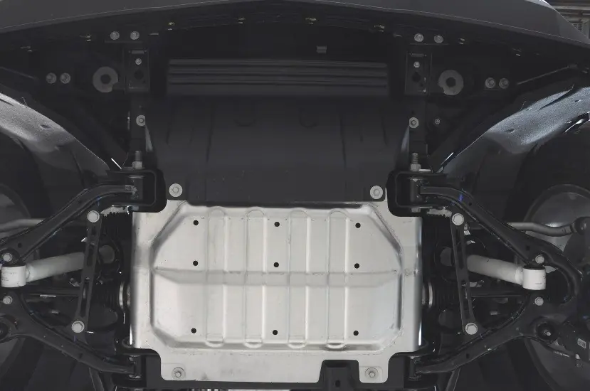
- Removing factory skid plates, tie-rod ends, brake lines, and ABS sensors.
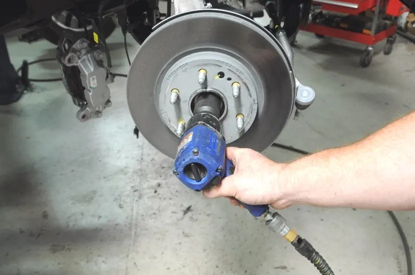
- Removing the CV axle nut, brake rotor, and knuckle assembly.
- Removing the sway bar, lower control arms, and front driveshaft.
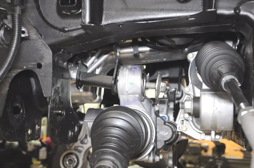
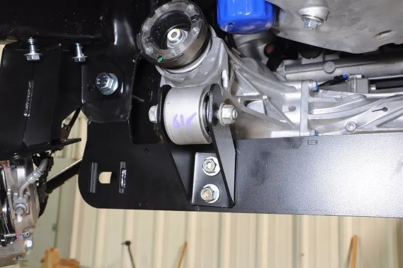
- Removing the rear crossmember and differential to install the supplied diff drop brackets.
- Trimming the driver-side rear crossmember mount as specified.
- Installing the new front and rear crossmembers, lower control arms, and strut spacers.
- Reassembling the suspension, including installing the new lifted knuckles, CV spacers, and tie-rod ends.
- Reconnecting all electrical components, including the rack and pinion and differential actuator.
- Installing the front and lower skid plates (note: models with an intercooler do not install the front skid plate).
Rear Suspension Installation
The rear installation focuses on lifting the rear suspension using blocks and U-bolts. Key steps include:
- Removing the rear shocks and brake line brackets.
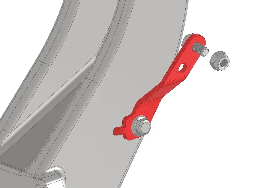
- Installing the supplied brake line drop brackets.
- Removing the stock U-bolts and lowering the axle.
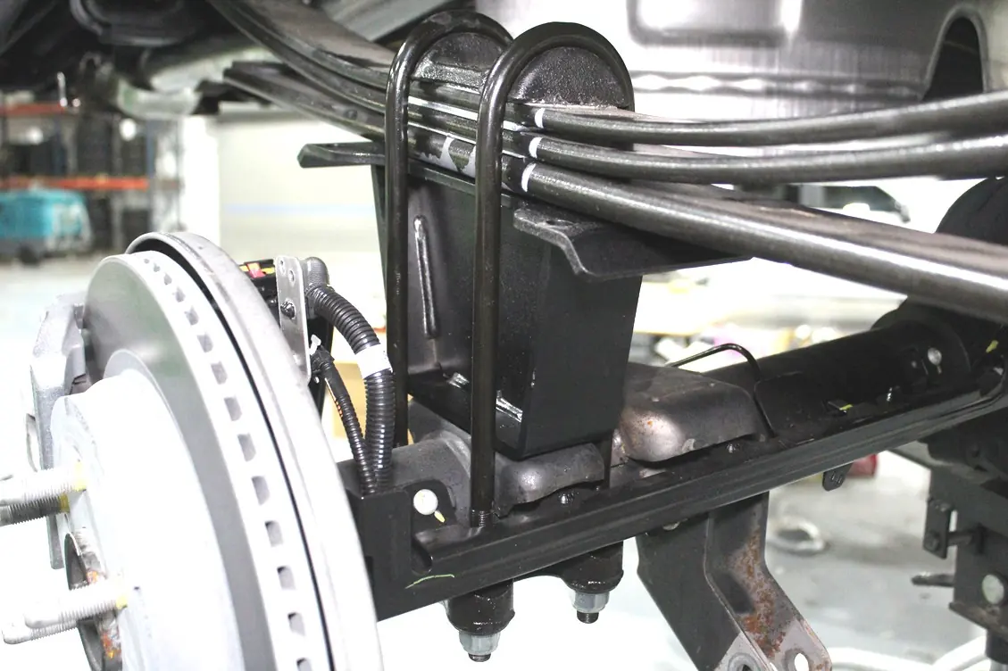
- Installing the new lift blocks with supplied 9/16" U-bolts, ensuring the short side of the block faces the front of the vehicle.
- Securing the lift blocks with 7/16" square U-bolts.
- Installing the new shock absorbers or relocating existing ones using the provided brackets for Adaptive Ride Control models.
Post-Installation Instructions
After installation, perform the following checks:
- Verify adequate clearance between all rotating, mobile, fixed, and heated members.
- Perform a steering sweep to ensure brake hoses have adequate slack.
- Have the vehicle aligned immediately by a qualified center to factory specifications (Caster: 4.0 +/- 1.0, Camber: -0.4 +/- 0.8, Toe In: 0.1 +/- 0.2).
- Check and retighten all wheels at 50 and 500 miles.
- Retighten all kit components at 500 miles and every 3,000 miles thereafter.
- Install the "Warning to Driver" decal on the sun visor.
Practical help
Common problems
Brake system error after wheel installation
Ensure wheels completely clear the brake caliper. Any pressure on the caliper will cause an error; the vehicle will require a reset by a GM dealership.
Electric power steering damage
Ensure all three connectors going to the rack and pinion are unplugged before removing any steering components.
Driveshaft boot damage
Do not allow the driveshaft to hang from the rear joint during removal; support it with a jack stand.
Before use
- Verify all kit hardware against the parts list.
- Ensure you have all required tools (e.g., 36mm socket, reciprocating saw).
- Park on a level surface and chock the rear wheels.
- Disconnect the battery.
- Check for adequate clearance between all rotating and fixed members.
Specs in practice
- Torque Specs
- Essential for safety; refer to the provided table for Grade 5/8 and Class 8.8/10.9 hardware.
- Alignment Specs
- Caster: 4.0 +/- 1.0, Camber: -0.4 +/- 0.8, Toe In: 0.1 +/- 0.2.
Images and diagrams
- Front Installation: Photos 1-82 show the step-by-step disassembly and reassembly of the front suspension, including diff drop brackets and crossmembers.
- Rear Installation: Photos 1-11 show the rear lift block and shock installation.
Model compatibility
- Fits crew cab short bed models only.
- Requires 35” x 12.5” tire with 20” x 9” wheel (offset -12mm or -6mm with 1/4” spacer).
- 20x10 wheels require -24mm or -18mm offset with 1/4” spacer.
- Max backspacing of 4.5”.

Manual page author
David Miller
Documentation analyst
Organizes user manual content into clear summaries, with attention to model details, product context, and everyday usability.