Automotive / Suspension Kits
Installation Instructions for ICON 58451DJ Tubular UCA DJ Kit
A comprehensive installation guide for the ICON 58451DJ Tubular UCA DJ Kit. This manual covers step-by-step mounting procedures, critical bushing lubrication requirements, torque specifications, and alignment recommendations for compatible...
Table of contents
Manual images
Click an image to enlargeQuick Guide
This document provides installation instructions for the ICON 58451DJ Tubular UCA DJ Kit. Important: All installation should be performed by a professional shop or service technician. Improper installation may result in severe frame, suspension, and tire damage. If your vehicle is equipped with the Kinetik Dynamic Suspension System (KDSS), it must be deactivated before beginning work and reactivated upon completion.
Components and Tools
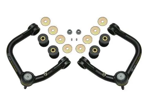
Ensure all components are present before starting. The kit includes tubular upper control arms (driver and passenger side), Delta Joints, sleeves, hat bushings, poly rings, and necessary hardware (washers, nuts, studs, zerk fittings, and spiral retaining rings).
Required Tools:
- Jack and Jack Stands
- Large Hammer or Hand Sledge
- Torque Wrench
- Needle Nose Pliers
- 7/64" Allen Wrench
- 10mm, 19mm, 21mm, and 3/8" Sockets/Wrenches
Installation Procedure
- If equipped with KDSS, deactivate the system according to the factory service manual.
- Raise the front of the vehicle using a properly rated jack and support the frame rails with jack stands. Remove the front wheels.
- Lift the lower control arm slightly to prevent the arms from being at full droop.
- Disconnect the upper ball joint: remove the cotter pin, loosen the nut (19mm) to the end of the shank, and dislodge the taper using a ball joint separator or by striking the spindle.
- Support the spindle to prevent overextending the CV joints.
- Disconnect the ABS line (10mm) from the arm, remove the ball joint nut, and disconnect the upper control arm from the spindle.
- Remove the large upper control arm pivot bolt (19mm). Note the direction and order of components. Remove the stock upper control arm.
Bushing Preparation and Final Assembly
Crucial Step: Before installing the new upper control arms, grease the bushings liberally. Failure to do so will cause premature bushing wear and increased noise.
- Install the new ICON tubular upper control arm into the chassis. Ensure the Delta Joint is oriented toward the back of the vehicle.
- Use the provided washers (150025) against the bushings and (605813) under the nut and bolt head. Feed the pivot bolt through the pivots and chassis tube.
- Grease the zerk fittings until grease is visible in the bushings, then tighten the pivot bolt to factory specifications.
- Pivot the Delta Joint stem to align with the spindle taper bore.
- Rotate the arm downward, install the stem through the spindle taper, and install the supplied flanged nut. Torque to 75 ft-lbs.
- Reattach the ABS line using the factory bolt.
- Install wheels, lower the vehicle, and torque to factory specifications.
- Repeat the process on the opposite side.
- Have the vehicle professionally aligned.
Maintenance and Alignment
Maintenance: ICON Delta Joints are pre-greased. Grease the Delta Joint every 3,000 miles or at every oil change. Add grease until old grease is expelled from the bottom of the assembly; wipe away excess.
Alignment Note: ICON upper control arms are engineered to allow for increased caster. Discuss with your alignment shop that you want the vehicle aligned with the caster at the maximum of the factory-recommended settings to take advantage of the dynamic effects.
Post-Installation: Verify all fasteners are properly torqued before driving. Retorque all nuts, bolts, and lugs after 100 miles and periodically thereafter.
Practical help
Common problems
Premature bushing wear and increased noise
Ensure bushings are greased liberally prior to installing the assembly.
KDSS system interference
Deactivate the KDSS system before performing any work on the vehicle and reactivate it after installation is complete.
Delta Joint stiffness
The new Delta Joint will be very stiff the first time you move it; this is normal.
Before use
- Verify vehicle compatibility (07+ FJ, 03+ 4Runner, 03+ GX).
- Ensure all required tools (Jack, Torque Wrench, Sockets) are available.
- Deactivate KDSS system if the vehicle is equipped with it.
- Grease bushings liberally before installing the arm assembly.
- Note the orientation of the arms (Delta Joint must face the back of the vehicle).
Specs in practice
- Taper pin torque
- 75 ft-lbs.
- Greasing interval
- Every 3,000 miles or every oil change.
Images and diagrams
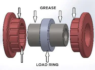
- Figure 1 illustrates the correct greasing points for the bushings and load ring.
Model compatibility
- Compatible with 07-UP FJ, 03-UP 4RNR, and 03-UP GX.
- Not intended for race, police, taxi, or commercial use.
- Warranty is void if components are not installed as a complete kit.

Manual page author
Michael Turner
Technical manual editor
Reviews PDF manuals for structure, safety notes, and practical product details so readers can find the right information quickly.