Electronics / Interactive Displays
User Manual for Philips 10BDL3351T Interactive Display
Quick start guide for the Philips 10BDL3351T Interactive Display. Includes installation instructions, port layout, control panel overview, and safety warnings.
Table of contents
Manual images
Click an image to enlargeQuick guide from the manual
This document provides essential setup and installation instructions for the Philips 10BDL3351T Interactive Display. It covers unboxing, hardware connections, mounting procedures, and safety compliance information.
Unboxing and Contents
Ensure your package contains the following items:
- Colour Display
- Quick Start Guide
- DC Power Adapter
- Power Plug (region-specific)
Device Overview
The device features a control panel and various input/output terminals for connectivity.
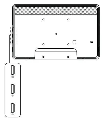
Control Panel
The control panel is located on the side of the display, providing physical buttons for basic operation.
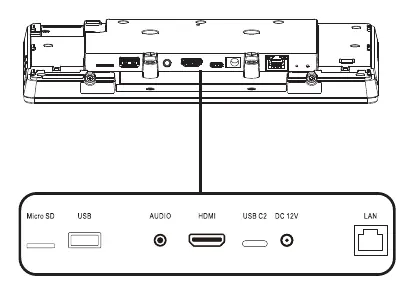
Input/Output Terminals
The rear of the device includes the following ports:
- Micro SD slot
- USB port
- Audio jack
- HDMI port
- USB-C port
- DC 12V power input
- LAN port
Installation
The display supports VESA mounting. Follow these steps for installation:
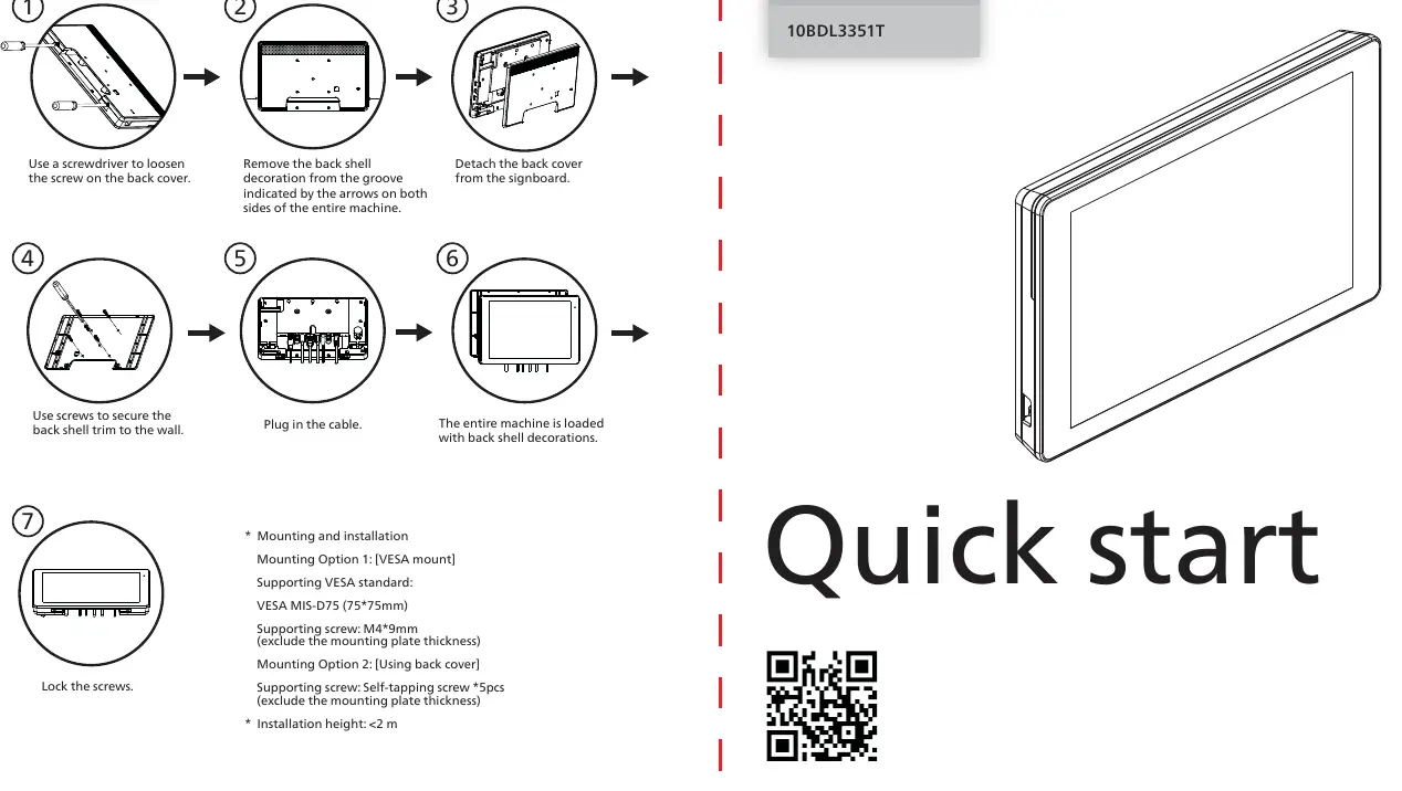
- Use a screwdriver to remove the screw on the back cover.
- Remove the back shell decoration from the groove indicated by the arrows on both sides.
- Detach the back cover from the signboard.
- Use screws to secure the back shell to the wall.
- Plug in the cable.
- The entire machine is loaded with back shell decorations.
- Lock the screws.
Mounting Specifications:
- Mounting Option 1 (VESA): Supports VESA MIS-D75 (75x75mm). Use M4x9mm screws (excluding mounting plate thickness).
- Mounting Option 2 (Back Cover): Use self-tapping screws (5pcs).
- Installation Height: Must be less than 2 meters.
Safety and Warnings
Battery Safety: Risk of explosion if the battery is replaced by an incorrect type. Do not dispose of the battery in fire or mechanically crush/cut it. Avoid leaving the battery in extremely high-temperature environments or extremely low air pressure.
Operating Environment: The suitable temperature for the display and accessories is 0°C-40°C.
FCC Compliance: This is a Class A digital device. Operation in a residential environment may cause radio interference, in which case the user will be required to correct the interference at their own expense.
Technical Specifications
- Power Adapter: Model ADS-26SGP-12 12024E, Input 100-240V~ 50/60Hz, Output 12.0Vdc 2.0A 24.0W.
- RF Specifications: Supports Bluetooth (2402-2480 MHz), 2.4G WiFi (2412-2472 MHz), and 5G WiFi (5150-5250 MHz, 5725-5850 MHz).
Manufacturer information
Philips
Practical help
Common problems
Radio interference in residential areas
This is a Class A device. If interference occurs, the user is responsible for correcting it.
Battery replacement safety
Risk of explosion if replaced by an incorrect type. Do not crush, cut, or expose to extreme heat or low pressure.
Before use
- Verify all contents: Display, Quick Start Guide, Power Adapter, and Power Plug.
- Ensure the installation environment temperature is between 0°C and 40°C.
- Check VESA mount compatibility (MIS-D75, 75x75mm).
- Ensure mounting height is less than 2 meters.
- Use only the provided power adapter with ferrite.
Specs in practice
- VESA MIS-D75
- Standard mounting pattern of 75mm x 75mm.
- Power Adapter Output
- 12.0Vdc, 2.0A, 24.0W.
- Class A Device
- Designed for commercial environments; may cause interference in residential areas.
Images and diagrams
- Control panel buttons are located on the side of the unit.
- Input/Output terminals are located on the rear, including HDMI, USB, and LAN ports.
Model compatibility
- Requires M4x9mm screws for VESA mounting (excluding plate thickness).
- Requires self-tapping screws for back cover mounting.

Manual page author
Michael Turner
Technical manual editor
Reviews PDF manuals for structure, safety notes, and practical product details so readers can find the right information quickly.