Baby / Children Products
User Manual for Regalo Arched Decor Safety Gate 0370BR / 0380BR
Quick guide for the Regalo Arched Decor Safety Gate (0370BR, 0380BR). Includes installation steps, door latch operation, wall cup mounting, and safety warnings.
Table of contents
Manual images
Click an image to enlargeQuick guide from the manual
The Regalo Arched Decor Safety Gate is a pressure-mounted gate designed for children aged 6 to 24 months. It requires adult assembly. Before installation, ensure you have all parts and that the mounting surface is drywall or wood. The gate must be installed level and centered. Always use base locks on both sides of the gate. The gap between the gate and the wall should not exceed 2.5 inches.
Parts List
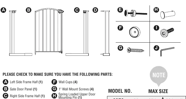
- Left Side Frame Half (A)
- Gate Door Panel (B)
- Right Side Frame Half (C)
- 4" Extension (D)
- Threaded Spindle Rods (E)
- Wall Cups (F)
- 1" Wall Mount Screws (G)
- Frame Assembly Screws (I)
- Hex Key (J)
- Spring Loaded Upper Door Mounting Pin (H)
Assembly and Installation
- Frame Assembly: Align the holes in the lower horizontal tube of the left (A) and right (C) frame halves. Tighten them together using the frame assembly screws (I).
- Door Insertion: Lower the gate door (B) into the assembled frame and insert the lower door pin into the mounting hole on the frame.
- Upper Pin: Align the hole in the upper corner of the gate door with the mounting bracket. Insert the spring-loaded mounting pin (H) into the bracket and door.
- Pressure Mounting: Insert the four threaded spindle rods (E) into the corners of the gate. Rotate the adjustment wheels to eliminate the gap between the wheel and the rubber foot.
- Positioning: Place the gate in the doorway. Rotate the adjustment wheels in the opposite direction to expand the rods until they make contact with the doorway. Do not fully tighten yet.
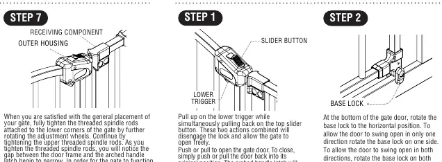
- Final Tightening: Tighten the lower rods first, then the upper rods. Stop tightening just before the outer housing of the arched handle latch and the receiving component touch.
Operating the Door Latch
To open the gate, pull up on the lower trigger while simultaneously pulling back on the top slider button. This disengages the lock. To close, simply push or pull the door back to its original position; the latch will re-engage automatically. Use the base locks at the bottom of the door to control the swing direction (one side or both sides).
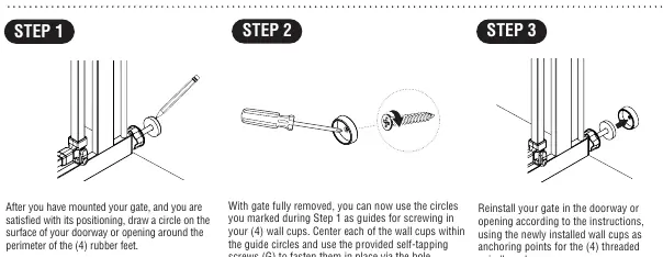
Wall Cup Installation
If you are satisfied with the gate's position, trace a circle around the perimeter of the four rubber feet. Remove the gate, center the wall cups (F) within the traced circles, and fasten them using the provided self-tapping screws (G). Reinstall the gate using the wall cups as anchoring points.
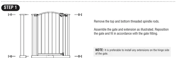
Adding a Gate Extension
Remove the top and bottom threaded spindle rods. Assemble the gate and extension as illustrated. Reposition the gate and fit according to the standard installation instructions. It is preferable to install extensions on the hinge side of the gate. Do not use more than two extensions per side.
Care and Maintenance
Periodically check the gate for damage, wear, or missing components. Do not use if any part is missing or damaged. Ensure all hardware is tightened regularly. Clean by sponging with warm water and a mild detergent. Do not use abrasive cleaners or bleach.
Practical help
Common problems
Gate latch not engaging
Ensure the gate is level, mounted properly, and that the threaded spindle rods are not over-tightened.
Gate feels unstable
Check that all hardware is tightened and that wall cups are used if the gate is at maximum width.
Gap between latch and frame
This is normal for pressure-mounted gates and is not a defect; the gap will disappear once the gate is properly tightened.
Before use
- Verify all parts (A-J) are present.
- Ensure the mounting surface is drywall or wood (consult a professional otherwise).
- Check that the gate is level and centered.
- Ensure base locks are used on both sides of the gate.
- Verify the gap between the gate and the wall does not exceed 2.5 inches.
Images and diagrams
- Step 1-3: Frame assembly and door insertion.
- Step 4-6: Pressure mounting using threaded spindle rods.
- Step 7: Final tightening and latch alignment.
Model compatibility
- Do not use more than two extensions per side.
- Extensions are sold separately.

Manual page author
David Miller
Documentation analyst
Organizes user manual content into clear summaries, with attention to model details, product context, and everyday usability.