Power / Batteries & Chargers
Installation Guide for RELiON InSight Series Fuel Gauge & Remote Button
A comprehensive installation and setup guide for the RELiON InSight Series Fuel Gauge and Remote Button. Includes step-by-step wiring instructions for 12V, 24V, and 48V battery systems, configuration diagrams, and troubleshooting for...
Table of contents
Manual images
Click an image to enlargeQuick Guide
This guide provides installation instructions for the RELiON InSight Series Fuel Gauge and Remote Button. These accessories are designed for use with InSight Series batteries. Important: InSight batteries should never be connected in series. Ensure all batteries are connected in parallel. The fuel gauge is constantly backlit and does not have an off switch.
What's Included

- 1x RELiON Fuel Gauge
- 1x Mounting Bracket
- 1x Fuel Gauge Cable Assembly (3m standard, 6m or 10m optional)
- 1x RELiON Remote Button Cable Assembly (3m standard, 6m or 10m optional)
- 1x CANBUS Splitter Cable
Fuel Gauge Installation
- Power down the device and the first InSight battery in the string by tapping the power button once, then depressing it until both LEDs show solid red (approx. 6 seconds).
- Attach the red ring terminal to the positive battery post and the black ring terminal to the negative battery post on the first battery.
- Insert the CANBUS plug from the cable assembly into the provided CANBUS SPLITTER.
- Route the other end of the cable through the mounting bracket to the dashboard. Insert the four-pin plug into the back of the gauge. Use zip ties to secure the harness and reduce strain.
- Insert the gauge through the dashboard, seat it in the mounting bracket, and rotate the bracket to hold it firmly in place.
Remote Button Installation
- Route the Remote Button Cable Assembly through the mounting hole to the battery compartment. Secure with zip ties.
- Attach the red ring terminal to the positive post and the black ring terminal to the negative post on the first InSight battery.
- Insert the CANBUS plug into the provided CANBUS splitter on the first battery.
- Insert the CANBUS splitter into the CANBUS IN port on the first battery.
- Test the button by depressing it until the batteries power on (approx. 5 seconds). LED 1 on all batteries will flash green.
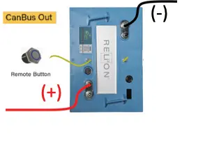
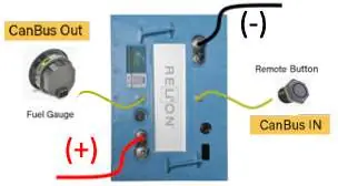
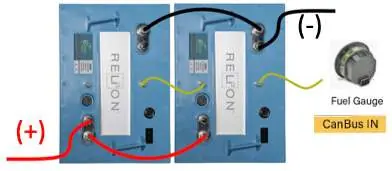
Wiring Configurations
The manual provides detailed diagrams for various setups, including single battery configurations and multi-battery strings. Always ensure the correct CANBUS port (IN or OUT) is used based on your specific setup. Termination resistors are required for certain multi-battery configurations. Refer to the provided diagrams for specific port connections.

Fuel Gauge Messages and Warnings
- Startup: Displays the number of batteries detected. Verify this matches your bank.
- Normal Operation: Displays state of charge (SOC) as a percentage (0-100%).
- Above 20% SOC: Displays SOC, number of batteries, and remaining amp hours.
- Below 20% SOC: Displays SOC and "LOBATT" message.
- At or below 10% SOC: Displays SOC and flashes "LOBATT" every 2 seconds.
- No Comms: Indicates incorrect setup or failure to read batteries.
Specifications
- Operating Current: 29 milliamps
- Operating Temperature: 14°F to 185°F (-10°C to 85°C)
- Storage Temperature: -40°F to 185°F (-40°C to 85°C)
- Ingress Protection: IP67
Practical help
Common problems
Gauge displays 'no comms'
The setup is incorrect or the gauge is not reading the batteries. Verify all CANBUS connections.
Batteries do not power on/off
Ensure the remote button is correctly connected to the IN port on the first battery in the string.
LOBATT message appears
The battery bank is below 20% state of charge. Charge the batteries.
Before use
- Power down the device and the first InSight battery.
- Ensure batteries are connected in parallel (never in series).
- Locate the correct cable assembly (Fuel Gauge or Remote Button).
- Have zip ties ready to secure harnesses to the vehicle.
- Verify the number of batteries in the bank matches the gauge detection at startup.
Specs in practice
- Operating Current
- 29 milliamps
- Operating Temperature
- 14°F to 185°F (-10°C to 85°C)
- Ingress Protection
- IP67 (dust tight and protected against immersion)
Images and diagrams
- Diagrams 1-9 illustrate various wiring configurations for single and multiple battery setups.
- Termination resistors are required for specific multi-battery configurations.
- The CANBUS splitter is optional depending on the specific battery setup.
Model compatibility
- Compatible with InSight Series batteries.
- Fuel gauge supports up to 14 batteries in parallel.
- Remote button supports up to 10 batteries in parallel.

Manual page author
Michael Turner
Technical manual editor
Reviews PDF manuals for structure, safety notes, and practical product details so readers can find the right information quickly.