Industrial / Electrical
Electronically Controlled Transmission Wiring Diagram and Service Guide
A technical guide for the Electronically Controlled Transmission system, featuring detailed wiring diagrams, system operation logic, service hints, and diagnostic voltage specifications for the engine control module.
Table of contents
Quick guide from the manual
This document provides technical wiring diagrams and operational logic for the Electronically Controlled Transmission system. It is intended for diagnostic and repair purposes, detailing how the Engine Control Module (ECM) interacts with transmission solenoids, sensors, and switches. Key information includes gear shift logic, lock-up operation, and diagnostic voltage values for troubleshooting.
System Operation
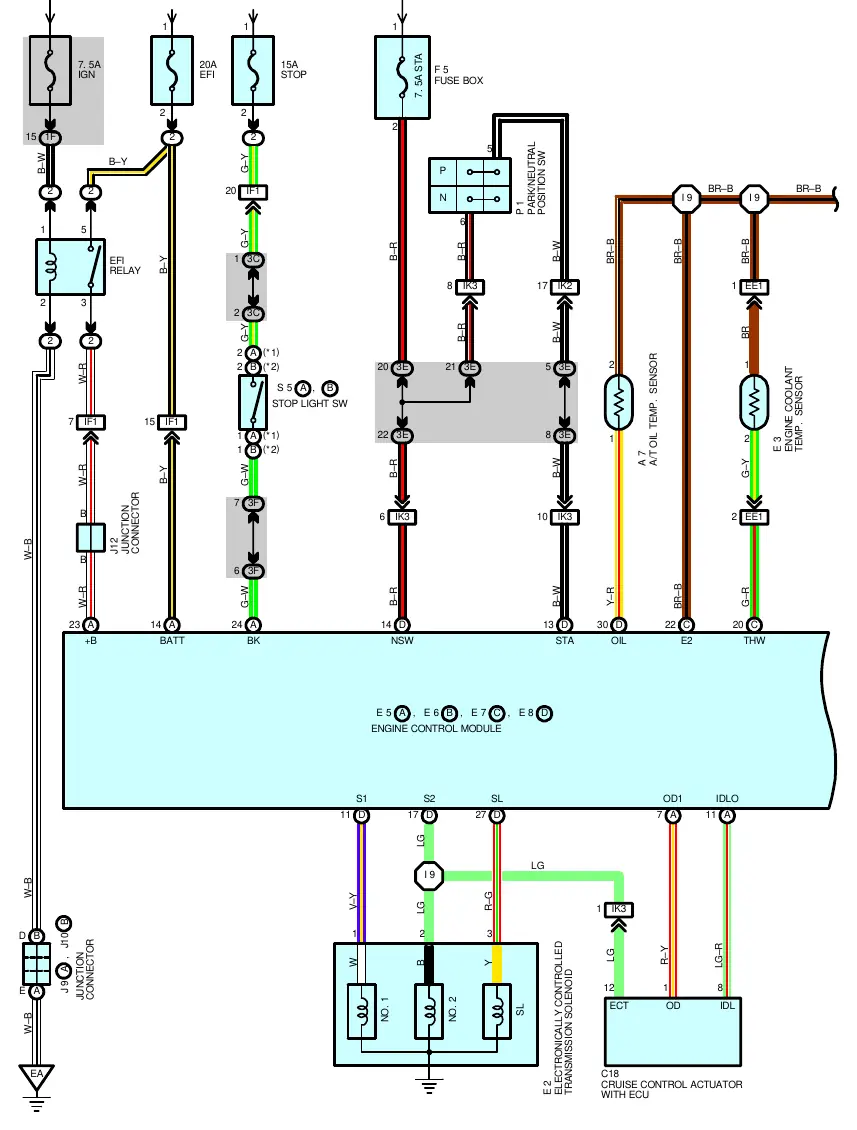
The transmission is electronically controlled to ensure smooth gear shifts based on driving conditions. The ECM processes input signals from the engine coolant temperature sensor and the vehicle speed sensor to determine the optimal gear.
- Gear Shift Operation: The ECM controls solenoids No.1 and No.2. Shifting is achieved by energizing these solenoids in specific combinations.
- Lock-up Operation: When conditions are met, the ECM energizes the lock-up solenoid via the SL terminal.
- Stop Light Switch Circuit: Depressing the brake pedal sends a signal to the ECM, which cuts continuity to the lock-up solenoid to disengage lock-up.
- Overdrive Circuit: Controlled by the O/D main switch. When off, the system prevents shifting into overdrive and illuminates the O/D off indicator.
- A/T Oil Temp Warning: If fluid temperature exceeds 150°C (302°F), the warning light illuminates. It turns off once the temperature drops to 120°C (248°F) or less.
Service Hints and Diagnostics
Use these specifications to test system components and wiring integrity:
- Solenoid Resistance: Approximately 13 ohms between terminals 1, 2, 3 and ground.
- Park/Neutral Position Switch: Approximately 12 volts at terminal 4-ground in ACC position.
- ECM Voltage Checks: The manual provides specific voltage ranges for terminals (e.g., S1-E1: 9-14V, THW-E2: 0.2-1.0V at 80°C). Always verify these values against the specific vehicle conditions listed in the service hints section.
Component Locations
The manual includes comprehensive tables mapping connector codes (e.g., A7, C10, E5) to their respective locations, such as the engine compartment, instrument panel, and kick panels. It also identifies ground points and splice points essential for tracing wiring faults.
Manufacturer information
Toyota Motor Corporation
Practical help
Common problems
A/T Oil Temp warning light is on
Check if transmission fluid temperature is above 150°C. If the light stays on at lower temperatures, inspect the A/T oil temp sensor and wiring.
Transmission fails to shift or lock-up
Verify voltage at ECM terminals S1, S2, and SL. Check solenoid resistance (approx. 13 ohms) and ensure the Park/Neutral position switch is functioning.
Overdrive not engaging
Check the O/D main switch status and input signal at terminal ODMS. Ensure the O/D off indicator is not active.
Before use
- Verify the vehicle model and engine type (e.g., 5VZ-FE) match the specific diagram page.
- Ensure the ignition is in the correct position (ACC or ON) before measuring voltages.
- Use a high-impedance multimeter for testing ECM terminal voltages.
- Check ground points (EA, EB, ID, IE, IG) for corrosion or loose connections if multiple electrical faults occur.
Specs in practice
- Solenoid Resistance
- 13 ohms; indicates the health of the transmission shift and lock-up solenoids.
- THW-E2 Voltage
- 0.2-1.0V at 80°C; monitors engine coolant temperature for shift timing.
- VTA-E2 Voltage
- 0.3-4.9V; indicates throttle position sensor status for load-based shifting.
Images and diagrams
- Lines represent wire harnesses; colors are abbreviated (e.g., B-R = Black-Red).
- Circles with letters/numbers indicate connector IDs.
- Arrows indicate signal flow direction between sensors, switches, and the ECM.
- Boxes labeled 'ENGINE CONTROL MODULE' show the central processing point for all transmission inputs and outputs.
Model compatibility
- Diagrams are specific to certain engine types (e.g., 5VZ-FE).
- Some circuits vary based on 'W/ CRUISE CONTROL' or 'W/O CRUISE CONTROL' configurations.
- Specific wiring differences exist for 4WD models.

Manual page author
David Miller
Documentation analyst
Organizes user manual content into clear summaries, with attention to model details, product context, and everyday usability.