Industrial / Logic Modules
Siemens LOGO! 0BA8 Logic Module User Manual
Quick guide for the Siemens LOGO! 0BA8 logic module. Learn about installation, wiring, programming, web server configuration, and technical specifications.
Table of contents
Manual images
Click an image to enlargeQuick guide from the manual
The Siemens LOGO! 0BA8 is a universal logic module designed for domestic and industrial automation. This manual covers installation, wiring, programming, and advanced features like the built-in web server.
Installation and Wiring
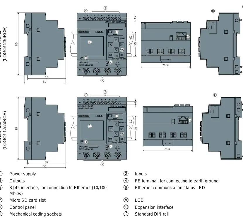
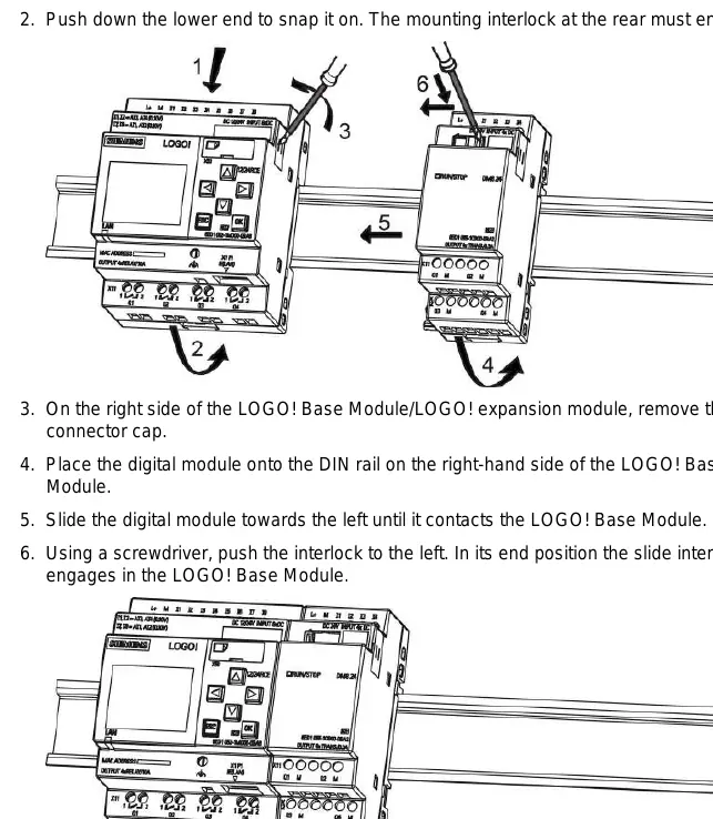
LOGO! modules are designed for fixed, enclosed installation in control cabinets. They can be mounted on a 35 mm DIN rail or wall-mounted using M4 screws.
- Safety: Always disconnect power before wiring or installing modules.
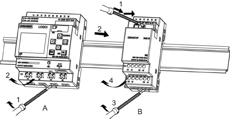
- Wiring: Use shielded cables for analog signals and keep them as short as possible. Connect the FE terminal to earth ground.
- Voltage Classes: Ensure expansion modules match the voltage class of the Base Module.
Programming
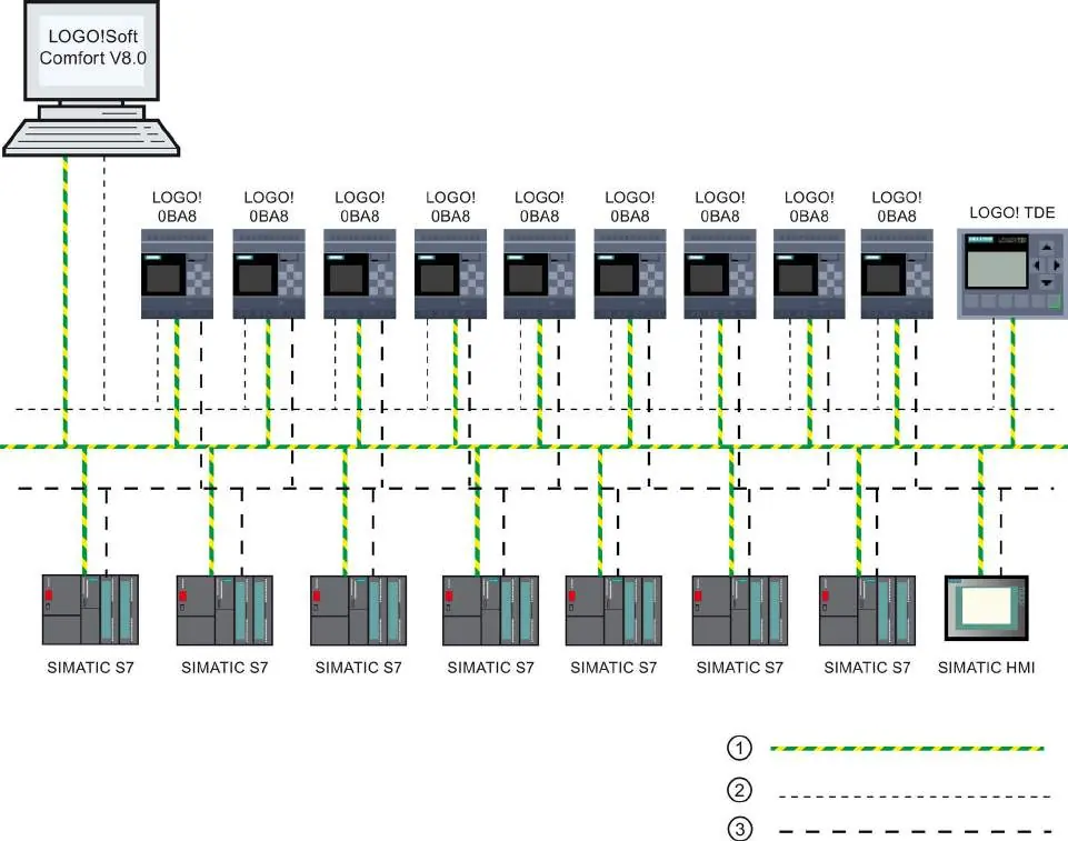
You can program the LOGO! directly using the onboard display or via PC using LOGO!Soft Comfort software. The system uses blocks and connectors to create circuit logic.
Web Server
The LOGO! 0BA8 features a built-in web server, allowing remote operation via a standard web browser. Ensure cookies are enabled and TCP port 8080 is configured for remote access.
Maintenance and Security
The device supports password protection and copy protection for circuit programs. Regularly check for firmware updates and maintain security by using strong passwords for web server access.
Manufacturer information
Siemens AG
Practical help
Common problems
Fluctuating analog values
Use shielded encoder wires, keep them under 10m, and clamp to the FE terminal on the expansion module.
Power failure during programming
The program in memory is lost; always save a backup copy to a card or PC using LOGO!Soft Comfort.
Expansion module not detected
Ensure power to the expansion module is switched on before or at the same time as the Base Module.
Before use
- Ensure power is off before wiring.
- Use shielded cables for analog signals.
- Connect the FE terminal to earth ground.
- Verify voltage class compatibility of expansion modules.
- Check that the sliding contact between modules is properly engaged.
Images and diagrams
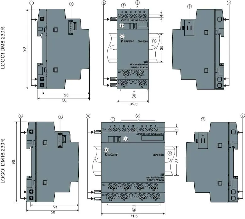
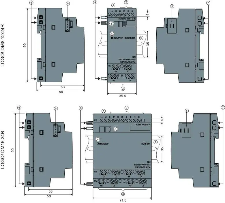
- Wiring diagrams show connections for DC and AC power supplies.
- The manual includes diagrams for DIN rail mounting and wall mounting.
- Timing diagrams illustrate the behavior of special functions like On-delay and Off-delay.
Model compatibility
- LOGO! 0BA8 is incompatible with previous device series.
- Expansion modules must match the voltage class of the Base Module.

Manual page author
Emily Carter
User documentation editor
Prepares concise manual descriptions and highlights the most useful setup, operation, and maintenance information for readers.