Hvac / Heat Pumps
Siemens LOGO! Ethernet Connection Guide
Comprehensive guide for connecting Siemens LOGO! series (0BA0 to 0BA8) via Ethernet, including HMI settings, software configuration, and device address mapping.
Table of contents
Overview of Siemens LOGO! Ethernet Connectivity
This guide provides instructions for establishing Ethernet communication between Siemens LOGO! programmable relays and HMI devices. The supported series include LOGO! 0BA0, 0BA1, 0BA2, 0BA7, and 0BA8 models. Proper configuration ensures reliable data exchange and multi-connection capabilities.
HMI and PLC Communication Settings
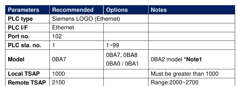
To establish a successful connection, specific parameters must be configured in the HMI software. The PLC type should be set to Siemens LOGO (Ethernet) using the Ethernet interface on port 102. The PLC station number is typically set to 1, with a valid range of 1 to 99. A critical aspect of the configuration is the TSAP (Transport Service Access Point) setting. The Local TSAP must be set to a value greater than 1000, while the Remote TSAP should be configured within the range of 2000 to 2700. For the 0BA2 model, ensure that the S7 access service is enabled to allow proper communication.
Configuring LOGO! Soft Comfort Software
Multi-connection settings require the use of LOGO! Soft Comfort software. Begin by navigating to the Tools menu and selecting Ethernet Connections. Right-click on the Ethernet Connections node and select Add connections to create a new link. The system allows for up to eight simultaneous connections. Once a connection is added, double-click it to configure it as a Server Connection. It is essential to tick the Accept all connection requests option to allow the PLC to communicate with any IP address. The Remote TSAP should be set to 10.00 for these connections.
Device Address Mapping
The guide includes detailed address mapping tables for different LOGO! models. These tables define the relationship between device types (such as Inputs, Outputs, Markers, and Analog values) and their corresponding VM (Variable Memory) addresses. For instance, the 0BA7 model uses specific mapping for I, Q, M, AI, AQ, and AM types. Similarly, the 0BA0 and 0BA8 models follow a structured byte-range mapping. Users should refer to these tables to ensure that the HMI correctly reads and writes data to the appropriate PLC memory locations. Always ensure that the Local and Remote TSAP values are set oppositely in the EasyBuilder software to maintain communication integrity.
Manufacturer information
Siemens AG
Practical help
Common problems
Communication failure between HMI and PLC
Verify that Local and Remote TSAP values are set oppositely in the HMI software and that the S7 access service is enabled on the PLC.
Unable to connect to multiple devices
Ensure that you have added multiple connections in LOGO! Soft Comfort (up to 8) and that 'Accept all connection requests' is enabled.
Before use
- Ensure LOGO! Soft Comfort software is installed
- Verify the specific LOGO! model (0BA0-0BA8)
- Confirm Ethernet cable is properly wired
- Check that port 102 is open and accessible
- Ensure PLC station number is unique (1-99)
- Confirm TSAP values are within the required ranges
Images and diagrams
- The Ethernet cable diagram shows the standard T568B wiring color code for RJ45 connectors.
- The software screenshots illustrate the path: Tools -> Ethernet Connections -> Add connections.
Model compatibility
- Supports Siemens LOGO! 0BA0, 0BA1, 0BA2, 0BA7, and 0BA8 series.
- 0BA2 model requires enabling S7 access service for communication.

Manual page author
David Miller
Documentation analyst
Organizes user manual content into clear summaries, with attention to model details, product context, and everyday usability.