Computers / Storage
User Manual for Silverstone Air Nexus 120 ARGB Case Fan
Quick guide for installing and connecting Silverstone Air Nexus 120 ARGB fans, including interlocking mechanism instructions and motherboard or hub connection steps.
Table of contents
Manual images
Jump to the sectionQuick guide from the manual
This document provides instructions for the installation and connection of the Silverstone Air Nexus 120 ARGB fans. It covers the interlocking mechanism for connecting multiple fans and the wiring procedures for both direct motherboard connection and optional PWM/ARGB hub usage.
Safety and usage conditions
- Do not hot-swap the fans while the system is running to avoid reducing their lifespan.
- Connect a maximum of 3 fans together to ensure optimal lighting and cooling performance.
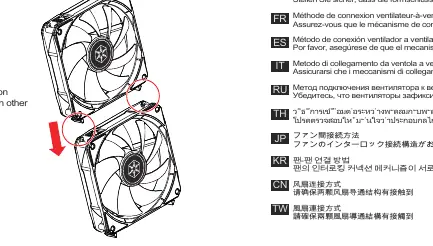
Fan-to-fan connection
The fans feature an interlocking connection mechanism. Ensure that the interlocking mechanisms of the fans are securely attached to each other before mounting them in your case.
Connection to the motherboard
For direct connection to the motherboard:
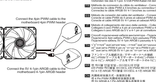
- Connect the 4-pin PWM cable to the motherboard's 4-pin PWM header.
- Connect the 5V 4-1 pin ARGB cable to the motherboard's 4-1 pin ARGB header.
Connection to PWM/ARGB hub
If using an optional PWM/ARGB hub:
- Connect the hub's SATA cable to the power supply unit (PSU) SATA connector.
- Connect the fan's 4-pin PWM cable and 4-1 pin ARGB cable to the hub's corresponding headers.
- Connect the hub's 4-1 pin ARGB cable to the motherboard's 4-1 pin ARGB header.
Manufacturer information
SilverStone Technology Co., Ltd.
Practical help
Common problems
Reduced fan lifespan
Do not perform hot-swapping (connecting or disconnecting while powered) of the fans.
Suboptimal lighting or cooling performance
Ensure you do not connect more than 3 fans in a single daisy-chained configuration.
Before use
- Verify that the interlocking mechanism is fully secured between fans.
- Check if your motherboard has a 4-pin PWM header and a 5V 4-1 pin ARGB header.
- If using a hub, ensure a SATA power connector is available from your PSU.
Specs in practice
- 5V 4-1 pin ARGB
- Addressable RGB connector for lighting control; ensure it is 5V, not 12V.
Images and diagrams
- Step 1 shows the direct wiring of PWM and ARGB cables to motherboard headers.
- Step 2 illustrates the interlocking mechanism used to join multiple fans together.
- Step 3 details the wiring path when using an optional PWM/ARGB hub, including SATA power connection.
Model compatibility
- The PWM/ARGB hub is an optional accessory and not required for basic operation.
- Ensure the ARGB header on the motherboard is 5V 4-1 pin type.

Manual page author
Michael Turner
Technical manual editor
Reviews PDF manuals for structure, safety notes, and practical product details so readers can find the right information quickly.