Automotive / Parts Accessories
User Manual for Sim-Lab XP-1 Pedal Set
Comprehensive user guide for the Sim-Lab XP-1 200KG Loadcell Pedal Set. Includes installation instructions, configuration of pedal base and face, software calibration via RaceDirector, and maintenance tips.
Table of contents
Manual images
Jump to the sectionQuick guide from the manual
The Sim-Lab XP-1 200KG Loadcell Pedal Set is a high-performance, fully customizable sim-racing pedal set. This manual covers the installation, mechanical configuration, and software setup required to get started. Key steps include mounting the pedals to your rig, adjusting the pedal base and face angles, configuring the brake and throttle feel, and calibrating the pedals using the RaceDirector software.
Installation
The pedals can be mounted directly to profile-based pedal decks (like the P1-X) or other pedal decks (like the GT1-EVO) using the 6mm slots located on the bottom of the pedal base. Ensure you use the provided mounting hardware. When mounting to a pedal slider baseplate, use the specific hardware indicated in the manual to protect the baseplate.
Configuration
Pedal Base: You can adjust the angle of the pedal arm by loosening the two pivot bolts (P) and the two arc bolts (A). This allows for a 20-degree range of adjustment. Ensure all four bolts are tightened securely before use, especially on the brake pedal.
Pedal Face: The position and angle of the pedal face can be adjusted. Loosen the two bolts (F) to change the position. To change the angle, loosen the top (T) bolts and remove the bottom (B) bolts to rotate the bracket, then re-secure.
Throttle configuration
The throttle spring can be adjusted for stiffness by unlocking the blue knobs and tightening the adjustment knob (A) clockwise for a stiffer feel. The travel can also be adjusted using the two blue knobs on the bottom of the pedal arm. The inner knob (L) is for locking, and the outer knob (A) is for adjustment. Ensure there is 3-4mm of clearance between the clevis fork and the pedal arm flange to prevent mechanical interference.
Brake configuration
The brake stack is customizable using different elastomers and preload springs. The medium elastomer (60A) is pre-installed. Available ratings are Soft (50A), Medium (60A), and Hard (70A). To change parts, remove the spring bolt (S) to release the clevis fork. If a spring makes noise after swapping, rotate it a quarter turn.
Clutch configuration
The clutch pedal shares base parts with the brake and throttle but uses a heavy spring. It is limited to the top two adjustment points on the pedal arm to prevent the clevis fork from colliding with the pivot. Adjustments should be made in small increments.
Control box
The control box can be mounted using the provided tabs. All pedal inputs are labeled. Connect the pedals to the control box and ensure the USB cable is plugged in last to ensure correct calibration on the first connection. If calibration issues occur, reset the control box by unplugging the USB cable, waiting a few seconds, and plugging it back in.
Maintenance
Regular cleaning and lubrication are recommended to maintain performance. Use WD-40 Specialist White Lithium Grease to lubricate moving parts, including the spring bolt and bushings.
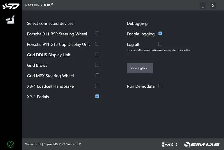
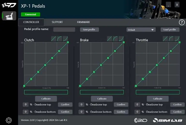
RaceDirector software
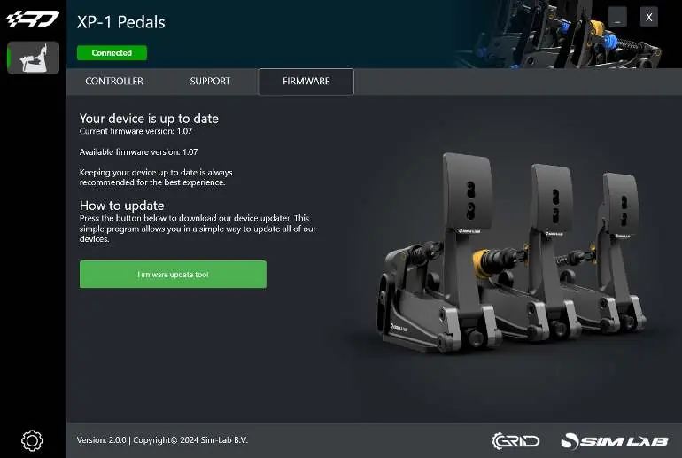
Download and install RaceDirector from www.sim-lab.eu/srd-setup. Activate the XP-1 Pedals on the Settings page. The device page allows for calibration, graph adjustment, and deadzone configuration. Press 'Calibrate' to enter calibration mode, press the pedal to maximum force, and finish. Firmware updates can be managed via the Firmware tab.
Accessories
The manual includes instructions for the Black conversion kit (replacing blue parts) and the Foot Support (installed between the pedal face and arm).
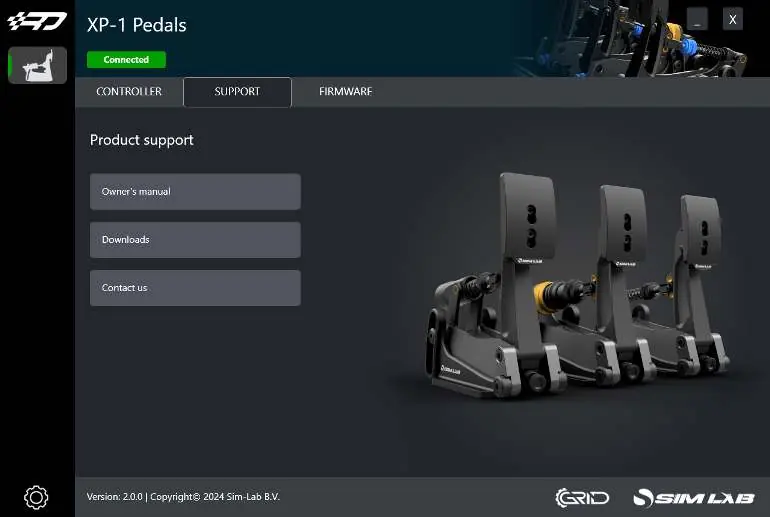
Official resources from the manual
Practical help
Common problems
Pedal makes noise when compressed
Rotate the spring a quarter turn or until the sound goes away.
Calibration issues
Reset the control box by unplugging the USB cable, wait a second or two, and plug it back in.
Clevis fork interfering with pedal arm flange
Reduce maximum travel until there is about 3-4mm of space between the flat base of the clevis fork and the pedal arm flange.
Before use
- Ensure all four bolts (A, P) on the pedal base are tight before using higher brake forces.
- Check pedal travel manually by hand to ensure no mechanical collision.
- Plug in the USB cable last to ensure correct calibration on the first connection.
- Install the latest version of RaceDirector from www.sim-lab.eu/srd-setup.
- Ensure the clevis fork does not collide with the pivot on the clutch pedal.
Images and diagrams
- Pedal base adjustment: Loosen bolts (P) and (A) to rotate the pedal arm.
- Pedal face adjustment: Loosen (F) for position; (T) and (B) for angle.
- Throttle adjustment: Use blue knobs (L) and (A) for spring tension and travel.
- Control box: Inputs are labeled for Throttle, Brake, and Clutch.
Model compatibility
- Compatible with profile-based pedal decks (e.g., P1-X) and pedal decks (e.g., GT1-EVO).
- Clutch pedal is sold separately.
- Mounting tabs on control box fit 80x40 pattern.

Manual page author
Emily Carter
User documentation editor
Prepares concise manual descriptions and highlights the most useful setup, operation, and maintenance information for readers.