Automotive / Parts Accessories
Sim Lab XP1 Pedals User Manual
Complete setup and configuration guide for Sim Lab XP1 Loadcell Pedals. Learn how to mount, adjust pedal feel, calibrate via RaceDirector, and maintain your equipment.
Table of contents
Manual images
Jump to the sectionQuick guide from the manual
The Sim Lab XP1 Pedals are a high-performance loadcell pedal set. To get started, mount the pedals to your rig, connect them to the control box, and install the RaceDirector software. Calibration is performed via the software interface. Ensure all bolts are tightened after making any mechanical adjustments to the pedal base, face, or brake stack.
Installation
The pedals can be mounted directly to profile-based pedal decks (like the P1X) or universal pedal decks (like the GT1 EVO). Use the 6mm slots on the bottom of the pedal base to bolt the set down. Ensure the mounting hardware is secure. When mounting to a pedal slider baseplate, use the provided washers to protect the surface.
Pedal configuration
Pedal Base: You can adjust the angle of the pedal arm by loosening the two pivot bolts (P) and the two arc bolts (A). Rotate the pedal to your preferred position (up to 20 degrees) and retighten all four bolts.
Pedal Face: Loosen the two bolts (F) to adjust the position of the pedal face. To change the angle, loosen the top (T) bolts, remove the bottom (B) bolts, rotate the bracket to the desired preset slot, and re-secure the bolts.
Throttle and brake setup
Throttle: Adjust spring stiffness by unlocking the blue knobs and tightening the adjustment knob (A) clockwise for a stiffer feel. Use the locking knob (L) to secure the setting. You can also adjust the maximum travel using the travel adjustment knob (A) on the bottom of the pedal arm.
Brake: The brake stack is customizable. Remove the clevis fork and shaft to access the elastomers and preload springs. The set includes three elastomer hardness ratings: Soft (50A), Medium (60A), and Hard (70A). Match your max pressure to the elastomer rating for durability. If a spring makes noise, rotate it a quarter turn.
Clutch configuration
The clutch pedal (sold separately) shares base parts with the brake and throttle. It is limited to the top two adjustment holes on the pedal arm. Ensure the clevis fork does not collide with the pedal arm during operation.
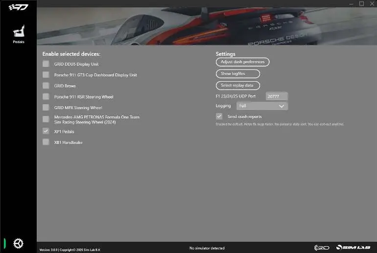
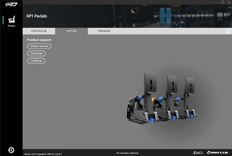
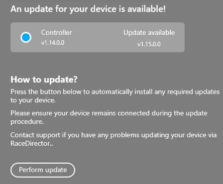
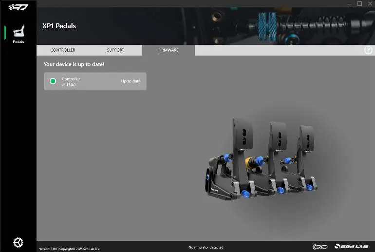
Control box and software
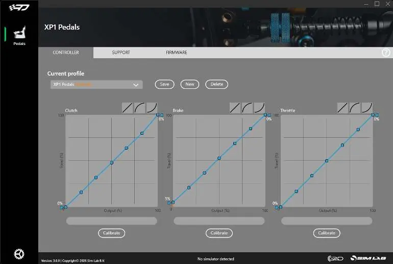
Connect all pedals to the control box using the labeled inputs. Plug the USB cable into your PC last to ensure correct calibration. Download and install RaceDirector from www.sim-lab.eu/srd-setup. Activate the XP1 Pedals in the settings page. Use the Controller tab to calibrate, adjust deadzones, and manipulate the input graph.
Maintenance
Clean and lubricate moving parts periodically. Use WD-40 Specialist White Lithium Grease on rotating and sliding parts, including the spring bolt bushing.
Accessories
Black conversion kit: Replace blue parts with black versions by following the installation guide provided in the kit.
Foot support: Install between the pedal face and pedal arm using the provided bolts. It is symmetrical and can be used on the throttle pedal.
Official resources from the manual
Practical help
Common problems
Pedal not calibrating correctly
Reset the control box by unplugging the USB cable, waiting 1-2 seconds, and plugging it back in.
Spring noise during compression
Rotate the spring a quarter turn or until the sound disappears.
Brake pedal feels too stiff or soft
Change the elastomer (50A, 60A, or 70A) or adjust the preload spring.
Clevis fork interfering with pedal arm
Reduce maximum travel using the travel adjustment knobs until there is 3-4mm clearance.
Before use
- Ensure all bolts are tightened after adjustments.
- Install RaceDirector software from the official website.
- Connect pedals to the control box before plugging USB into PC.
- Check for mechanical clearance to avoid parts colliding.
- Verify the correct elastomer is installed for your preferred brake feel.
Specs in practice
- 50A Elastomer
- Soft feel, recommended for lower brake pressures.
- 60A Elastomer
- Medium feel, pre-installed.
- 70A Elastomer
- Hard feel, recommended for high brake pressures.
- 16-Bit resolution
- High precision input for accurate simulation.
Images and diagrams
- Pedal base adjustment: Loosen bolts (P) and (A) to rotate the pedal arm.
- Pedal face adjustment: Loosen bolts (F) to change position; remove (B) and loosen (T) to change angle.
- Control box ports: Labeled inputs for Throttle, Brake, Clutch, and Ext.
Model compatibility
- Clutch pedal sold separately.
- Mounting tabs fit 80x40 pattern.
- Compatible with profile-based pedal decks and universal baseplates.

Manual page author
Michael Turner
Technical manual editor
Reviews PDF manuals for structure, safety notes, and practical product details so readers can find the right information quickly.