Electronics / Data Center Infrastructure
StarTech.com 18HE Knock-Down Server Rack Cabinet RK1836BKF
Quick guide for the StarTech.com 18HE Knock-Down Server Rack (RK1836BKF). Includes assembly instructions, safety warnings, grounding procedures, and equipment installation steps.
Table of contents
Manual images
Click an image to enlargeQuick guide from the manual
This document provides assembly and installation instructions for the StarTech.com 18HE Knock-Down Server Rack (RK1836BKF). Always ensure the floor surface is level and capable of supporting the combined weight of the rack and installed equipment. Weight capacity: Stationary = 800 kg, Rolling = 150 kg. This product is for indoor use only and requires a proper grounding connection.
Product Overview
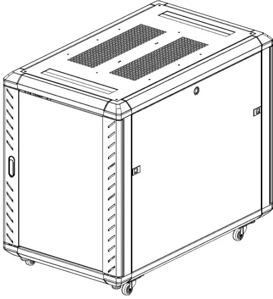
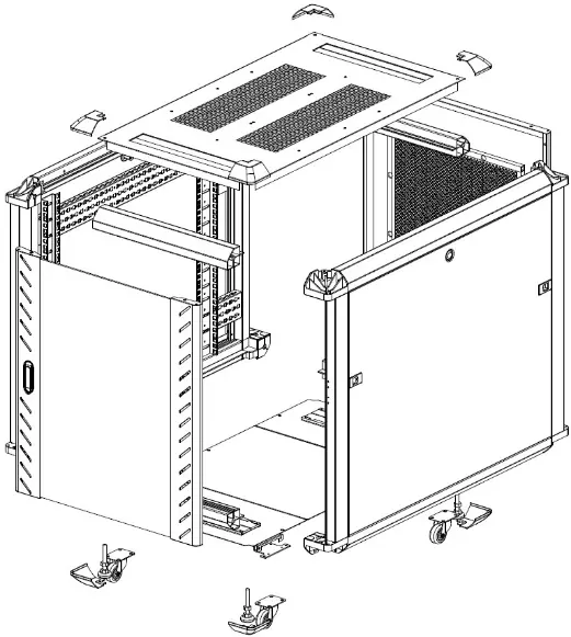
The rack consists of side panels, top and bottom plates, front and rear doors, and mounting rails. Refer to the product diagram to identify components such as the leveling feet, casters, and corner caps.

Assembly Instructions
The assembly process involves several stages:
- Frame Assembly: Align side panels with center beams. Secure using M8 x 20 mm bolts and spring washers. Ensure the lip on the beams aligns with the side panel.
- Casters and Leveling Feet: Invert the rack frame. Attach casters to the bottom corners using M6 x 10 mm screws. Install leveling feet into the threaded holes on the bottom frame.
- Top and Bottom Panels: Attach the top plate and bottom plates (with cable management slots) to the frame using the provided M6 screws.
- Doors: Install the door hinge pins into the side panels. Align the front and rear doors with the hinge pins and secure the spring-loaded pins.
Leveling and Grounding
Before installing equipment, the rack must be leveled to ensure stability. Use a spirit level to check the surface. Lower the leveling feet using a 14 mm wrench until they bear the weight of the rack and are shorter than the casters. Grounding: You must connect an earth ground cable to the grounding point located on the inside of the bottom of the front/rear doors and side panels.
Equipment Installation
When loading equipment, always place the heaviest items in the bottom rails to maintain stability. Use the provided M6 cage nuts and screws. Insert cage nuts into the mounting rails, align the equipment, and secure with screws.
Adjusting Mounting Rails
The mounting rails can be adjusted for depth:
- Remove the four M6 screws securing the mounting rail to the depth adjustment rails.
- Remove the cage nuts from the depth adjustment rails.
- Slide the mounting rail to the desired depth.
- Re-insert the cage nuts and secure the mounting rail with the M6 screws.
Official resources from the manual
Practical help
Common problems
Rack instability
Ensure the floor is level and adjust the leveling feet until they firmly contact the floor and support the rack's weight.
Difficulty removing cage nuts
Use a cage nut tool if available, or press the two prongs on the back of the cage nut inward to release it.
Tipping hazard
Never extend more than one component from the rack at a time.
Before use
- Verify the floor can support the total weight of the rack and equipment (800 kg stationary / 150 kg rolling).
- Ensure you have a spirit level, 14 mm wrench, and a Phillips screwdriver.
- Check that all parts listed in the package contents are present.
- Confirm the installation site is indoors and on a flat, even surface.
Specs in practice
- Weight Capacity (Stationary)
- 800 kg maximum load when the rack is stationary.
- Weight Capacity (Rolling)
- 150 kg maximum load when the rack is being moved on casters.
- Rail Adjustment
- Mounting rails can be repositioned along the depth adjustment rails by removing M6 screws.
Images and diagrams
- The product diagram identifies key components: 1. Top Panel, 2. Plastic Corner Caps, 3. Center Beam, 4. Front Door, 5. Casters/Leveling Feet, 6. Bottom Plate, 7. Side Panel, 8. Rear Door.
Model compatibility
- Requires a protective earth ground connection.
- Designed for indoor use only.

Manual page author
David Miller
Documentation analyst
Organizes user manual content into clear summaries, with attention to model details, product context, and everyday usability.