HVAC / Heaters & Fireplaces
User Manual for Stelpro Oxford Series Agricultural Unit Heater
Comprehensive user guide for the Stelpro Oxford Series agricultural unit heater. Includes installation instructions, electrical wiring diagrams, operation modes, maintenance procedures, and troubleshooting steps for models SFH0521DIS...
Table of contents
Manual images
Click an image to enlargeQuick guide from the manual
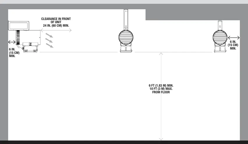
This manual covers the installation, operation, and maintenance of the Stelpro Oxford Series agricultural unit heaters. Key safety requirements include installing the unit at a minimum height of 6 ft (1.83 m) and a maximum of 10 ft (3 m) from the floor. Ensure a minimum clearance of 24 in. (60 cm) under the unit and 6 in. (15 cm) on each side to prevent overheating. The unit must be installed by a certified electrician in accordance with local electrical and building codes.
Installation
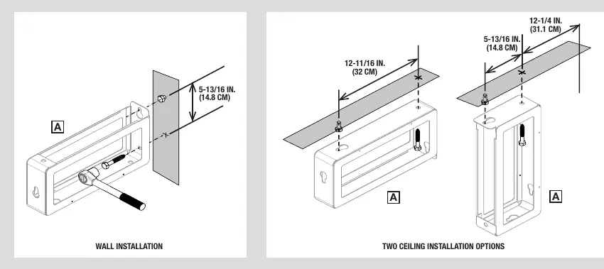
The unit and bracket weigh 35 lbs (16 kg). Ensure the mounting surface can support this weight. Use a stud finder to locate ceiling or wall studs for secure mounting. The mounting bracket must be attached to a stud. Follow the specific diagrams provided for wall or ceiling installation options. Ensure the bracket is level before attaching the heater.
Electrical Connection
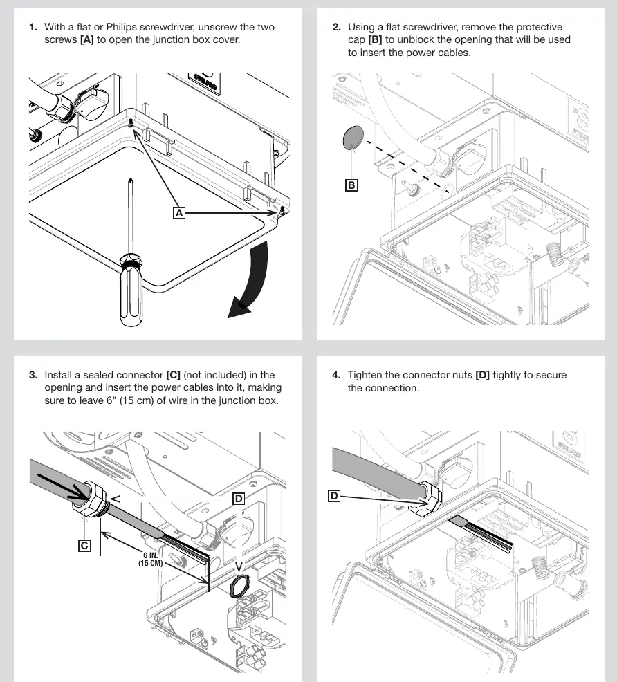
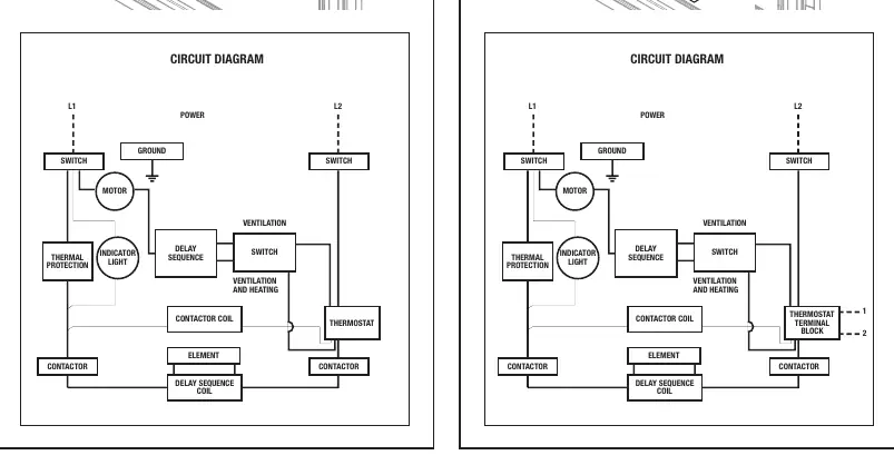
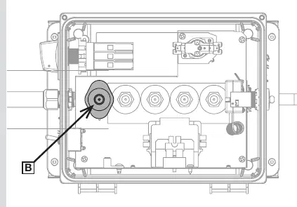
Before connecting, turn off the power supply at the electrical panel. Open the junction box cover by unscrewing the two screws. Remove the protective cap to unblock the opening for power cables. Install a sealed connector (not included) and insert the power cables, leaving 6 in. (15 cm) of wire inside the junction box. Connect the power supply and thermostat wires according to the specific circuit diagram for your model (with or without built-in thermostat). Ensure all terminal screws are tightened firmly.
Operation
The unit features a main switch to turn off power supply. Models SFH0521TDIS and SFHGX0521TDIS include a built-in thermostat for temperature control. Model SFH0521DIS requires an external wall line volt thermostat. An operation mode selector switch allows choosing between Ventilation only mode or Ventilation and heating mode. The unit includes a time-delay feature to cool heating elements after the setpoint is reached.
Maintenance
Regular cleaning of the air inlet and outlet is required for warranty validity. Turn off power at the electrical panel before cleaning. Dust the unit with a soft cloth or use a vacuum cleaner with a dust brush in dusty areas. The unit is water-resistant and can be hosed down. Never use metal brushes, scouring pads, chlorine, abrasive cleaning products, or hydrochloric-acid based products.
Troubleshooting
If the unit does not start, check the setpoint, wiring connections, and ensure the circuit breaker and main switch are ON. If the circuit breaker trips, verify wiring and ensure the breaker/fuse is adequate for the power required. If the unit is not heating, check for obstructions at the air inlet/outlet and ensure the thermal protection has not been triggered. For model SFHGX0521TDIS, refer to the thermal protection reset procedure if overheating occurs.
Practical help
Common problems
Unit does not start after installation
Check if the setpoint is too low, verify wiring connections, and ensure the circuit breaker and main switch are ON.
Circuit breaker trips when switched on
Verify wiring connections, check that the electrical voltage matches the nameplate, and ensure the circuit breaker/fuse is adequate.
Unit is not heating
Check for obstructions at air inlet/outlet, verify setpoint, and check if thermal protection has been triggered.
Indicator light is on
Indicates overheating or thermal protection trigger. Clear obstructions and allow the unit to cool.
Before use
- Ensure installation height is between 6 ft (1.83 m) and 10 ft (3 m) from the floor.
- Maintain 24 in. (60 cm) clearance under the unit and 6 in. (15 cm) on each side.
- Verify that the mounting surface can support 35 lbs (16 kg).
- Confirm electrical supply voltage matches the unit's nameplate.
- Ensure the unit is properly grounded.
- Have a certified electrician perform the installation.
Specs in practice
- Heating Capacity
- Recommended 1.25 W/cubic foot (approx. 10 W/square foot for 8 ft ceiling).
Images and diagrams
- Wiring diagrams are provided for both models with built-in thermostats and those requiring external thermostats.
- Installation diagrams illustrate both wall and ceiling mounting configurations.
Model compatibility
- SFH0521DIS: Requires an external wall line volt thermostat.
- SFH0521TDIS and SFHGX0521TDIS: Include a built-in thermostat.
- Suitable for Category 1 and 2 locations (corrosive vapors/liquids or excessive humidity).

Manual page author
Michael Turner
Technical manual editor
Reviews PDF manuals for structure, safety notes, and practical product details so readers can find the right information quickly.