Lighting / Outdoor Lighting
Telran 4+2 100Mbps PoE Switch
Quick guide for the Telran 4+2 100Mbps PoE Switch. Learn about installation, DIP switch modes (Default/CCTV), LED indicators, and technical specifications.
Table of contents
Manual images
Click an image to enlargeQuick guide from the manual
The Telran 4+2 100Mbps PoE Switch is an unmanaged network device designed to provide seamless connectivity and power to IEEE 802.3af/at compliant devices such as IP cameras, access points, or IP phones. It features 4 PoE ports and 2 uplink ports, with a selectable DIP switch for standard or CCTV operation modes.
Hardware Description
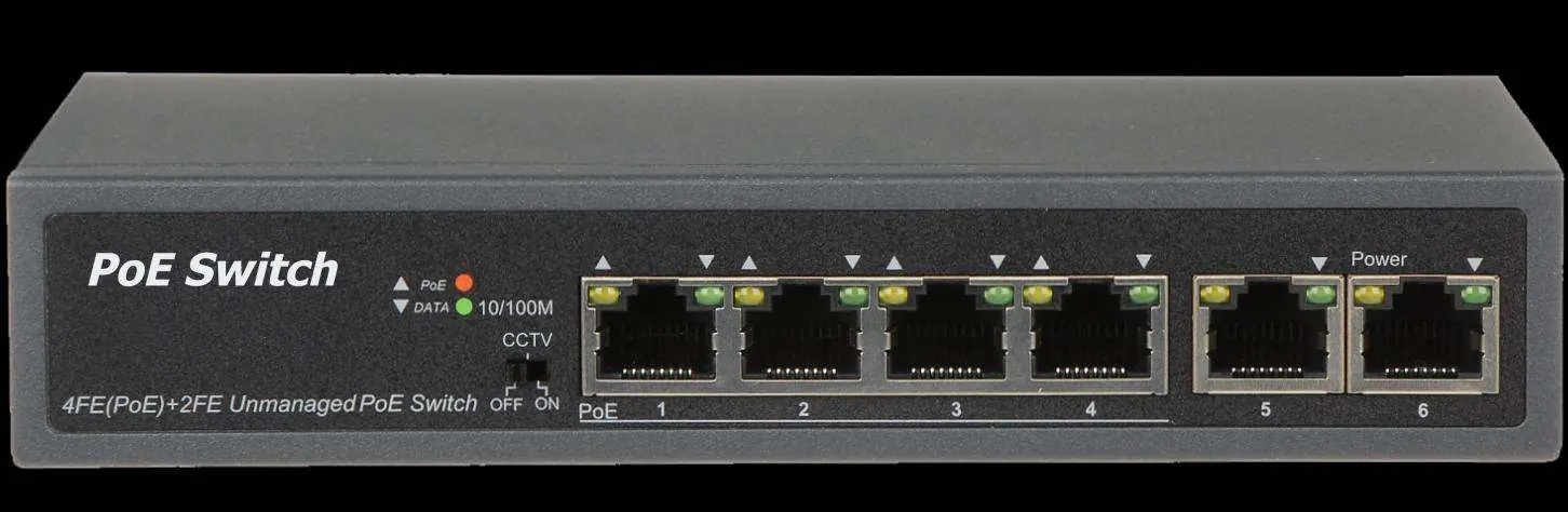
The front panel features 6 RJ45 Ethernet ports. Ports 1-4 are PoE-enabled, while ports 5-6 are standard uplink ports. LED indicators for Power, Data, and PoE status are located on the left side of the panel.
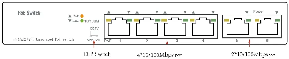
DIP Switch Settings
The DIP switch on the left panel allows you to toggle between two modes:
- Default mode: Standard communication between all ports (1-6).
- CCTV mode: Isolates ports 1-4 from each other but allows them to connect to ports 5 and 6. This mode helps stop broadcast storms and extends the PoE transmission distance up to 250 meters.
Note: You must manually restart the switch after changing the DIP switch mode for the configuration to take effect.
LED Indicators
- PWR (Orange): Indicates the switch has power.
- DATA (Green): Indicates a successful link at 10/100Mbps. Blinking indicates active data transmission.
- PoE (Orange): Indicates a PoE device is connected and receiving power. Blinking indicates abnormal power supply.
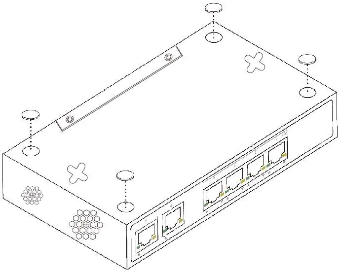
Installation
Desktop Installation: Attach the provided rubber feet to the bottom corners of the switch to prevent vibration and ensure adequate ventilation space.
Wall-mounted installation: Secure two screws into the wall, then align the switch's mounting holes with the screws and slide the unit into place.
Safety and Maintenance
- Always unplug the power cord before cleaning.
- Do not clean the device with wet cloths or liquids.
- Ensure the operating voltage matches the label on the device.
- Keep ventilation vents free of obstructions to prevent overheating.
- Do not place the device near water, damp areas, or on unstable surfaces.
Specifications
- Standards: IEEE802.3, IEEE802.3u, IEEE802.3x, IEEE802.3af, IEEE802.3at
- PoE Ports: Port 1-4
- PoE Output: 30W (Max)
- Switching Capacity: 1.2G
- Dimensions: 168 x 93 x 32 mm
- Operating Temperature: 0°C to 40°C
Practical help
Common problems
Device configuration not applying
You must manually restart the PoE switch after changing the DIP switch mode.
No power indicator
Check the power cord connection and ensure the outlet is providing power.
PoE device not powering on
Ensure the connected device is IEEE 802.3af/at compliant and check that the cable is not damaged.
No data link
Check that the Ethernet cable is securely connected to both the switch and the end device.
Before use
- Verify package contents: Switch, Power Cord, and 4 rubber feet.
- Ensure the operating voltage matches the label on the switch.
- Choose a stable location for desktop or wall mounting.
- Ensure adequate ventilation space around the device.
- Keep the device away from water or damp environments.
Specs in practice
- PoE Power on RJ45
- Uses Mode A (pins 1/2 positive, 3/6 negative).
- Transfer mode
- Store-and-Forward switching.
Images and diagrams
- The front panel diagram identifies the location of the DIP switch, PoE ports (1-4), and uplink ports (5-6).
- The rear panel diagram shows the location of the AC power inlet.
- The installation diagrams illustrate where to attach the rubber feet for desktop use and how to align the unit for wall mounting.
Model compatibility
- Supports IEEE 802.3af/at compliant Powered Devices (PD).
- 10BASE-T requires UTP category 3, 4, or 5 cable.
- 100BASE-TX requires UTP category 5 cable.

Manual page author
Emily Carter
User documentation editor
Prepares concise manual descriptions and highlights the most useful setup, operation, and maintenance information for readers.