Automotive / Parts & Accessories
Wiring Diagram for Back-Up Light - 2002 Toyota Celica
Official wiring diagram and service information for the back-up light system of the 2002 Toyota Celica. Includes circuit paths, switch operation logic, connector locations, and ground points for troubleshooting.
Table of contents
Quick Guide to Back-Up Light Wiring
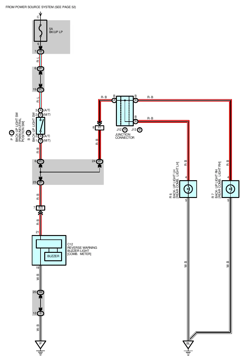
This document provides the electrical wiring diagram and service specifications for the back-up light system in the 2002 Toyota Celica. It details the circuit path from the power source to the rear combination lights and the reverse warning buzzer.
Circuit Overview
The back-up light circuit is protected by a 5A fuse labeled BK/UP LP. The circuit is activated by a back-up light switch that closes when the transmission shift lever is placed in the Reverse (R) position. The system includes a reverse warning buzzer (C12) located in the combination meter.
Service Hints and Switch Operation
To troubleshoot the back-up light system, verify the operation of the switch based on the transmission type:
- Automatic Transmission (A/T) - Switch P1: The switch is closed when the shift lever is in the R position. Test continuity between terminals 3 and 2.
- Manual Transmission (M/T) - Switch B1: The switch is closed when the shift lever is in the R position. Test continuity between terminals 2 and 1.
Connector and Ground Locations
The system utilizes several junction blocks and connectors to route wiring throughout the vehicle. Key locations include:
- Junction Blocks: IB, II, IM, 2C, 2F.
- Connector Joining: IE5 (Engine Room Main Wire and Instrument Panel Wire) and II1 (Engine Room Main Wire and Floor Wire).
- Ground Points: IF (Instrument Panel Brace RH) and BL (Back Panel Center).
Manufacturer information
Toyota Motor Corporation
Practical help
Common problems
Back-up lights fail to illuminate
Check the 5A BK/UP LP fuse. If the fuse is intact, test the back-up light switch (P1 or B1) for continuity when the shift lever is in the R position.
Reverse warning buzzer not sounding
Verify the connection to the C12 buzzer in the combination meter and ensure the back-up light switch is functioning correctly.
Before use
- Verify the 5A fuse is not blown.
- Ensure the vehicle is in the Reverse (R) position when testing the switch.
- Check ground points IF and BL for secure connection.
- Identify if the vehicle is Automatic (A/T) or Manual (M/T) to test the correct switch (P1 or B1).
Images and diagrams
- The diagram illustrates the power flow from the source, through the switch, to the rear combination lights (R6, R7) and the reverse warning buzzer (C12).
Model compatibility
- Applicable to 2002 Toyota Celica models.

Manual page author
Michael Turner
Technical manual editor
Reviews PDF manuals for structure, safety notes, and practical product details so readers can find the right information quickly.