Garden / Lawn Mowers
User Manual for Texas Pro Trac 1350BE Universal Tractor
Quick guide for the Texas Pro Trac 1350BE universal tractor. Includes setup, operation, maintenance, safety instructions, and troubleshooting.
Table of contents
Manual images
Click an image to enlargeQuick guide from the manual
This manual provides essential instructions for the Texas Pro Trac 1350BE. Before starting, ensure the engine is filled with SAE-30 oil and the fuel tank contains unleaded 95 octane gasoline. Always operate the machine from the designated safety zone behind the handlebar. If you need to leave the safety zone, stop the engine first.
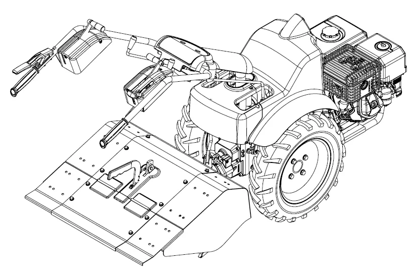
Parts Identification
- A: Engine
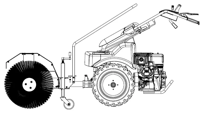
- B: Brush (accessory)
- C: Rod for angle adjustment of brush
- D: Quick release lock for handlebar
- E: Direction lever (forward/reverse)
- F: Throttle lever
- G: Quick coupling lever
- H: Clutch handle
- I: Differential lever
- J/K: PTO/Gear shifter
- L: Height adjustment lock
Starting and Stopping
Starting:
- Open the fuel valve (A).
- Set the throttle lever to max (C).
- For cold starts, set the choke arm (B) to "Choke".
- Pull the start cord (E) until resistance is felt, then pull firmly.
- Once started, set the choke to "Run".
- For electric start models, turn the ignition key (F).
Stopping:
- Release the clutch handle (G).
- Set the throttle control to "low" (C).
- For electric start models, turn the ignition key to "0".
Operation
The machine features a differential system to assist with turning. Both wheels can be locked if the machine needs to travel in a straight line or if wheels are slipping. Use the PTO shifter to engage accessories. Always clear the area of obstacles before reversing.
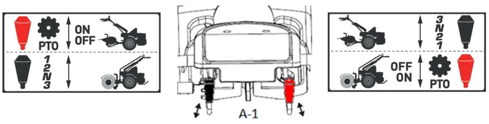
Mounting Accessories
The machine supports both front and rear-mounted accessories. To change configuration:
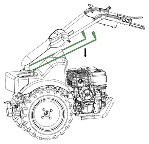
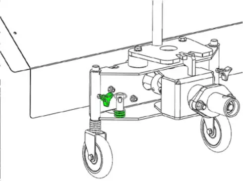
- Set gear to neutral (N) and release shifter rods.
- Remove the PTO shifter rod (A) by removing the spring clip (C).
- Rotate the tube (B) 180 degrees.
- Adjust the handlebar lock (A) and rotate the handle 180 degrees.
- Important: A safety bolt is installed in the right panel box for rear-mounted accessories to prevent high reverse speed. This must be removed when using front-mounted accessories.
Maintenance
- Oil Change: Change oil after the first 5 hours, then annually or every 20 hours. Use SAE-30 oil.
- Lubrication: Keep gears greased. Lubricate the quick coupling via the grease nipple with 1-2 presses.
- Storage: Clean the machine with a damp cloth. Avoid high-pressure washers. Store in a dry, clean location.
Troubleshooting
- Motor will not start (manual): Check fuel control, spark plug, and fresh fuel.
- Motor will not start (electric): Check fuel, spark plug, ground connection, or use recoil starter.
- Blades will not rotate: Check for lodged stones or cable condition.
Practical help
Common problems
Motor will not start (manual)
Check fuel control, spark plug, and ensure fresh fuel is in the tank.
Motor will not start (electric)
Check fuel, spark plug, ground connection, or use the recoil starter if the battery is discharged.
Blades will not rotate
Check for stones lodged between blades and verify cable condition.
Motor running unevenly
Ensure throttle is not set to max (choke) and check for fresh fuel.
Before use
- Check engine oil level (SAE-30).
- Ensure fuel tank is filled with unleaded 95 octane.
- Clear work area of foreign objects.
- Check all bolts and nuts are tightened.
- Verify safety zone is clear.
Specs in practice
- Displacement
- 420 cc
Images and diagrams
- Illustration 1: Parts identification (A-L).
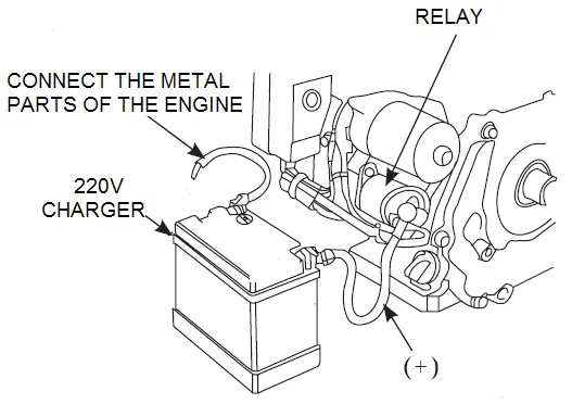
- Illustration 2: Battery ground wire connection.
- Illustration 5: Operation procedure (Gear, Throttle, Direction, Clutch).
- Illustration 7/8: Changing between front and rear mounted accessories.
Model compatibility
- Compatible with various front and rear mounted accessories (tiller, sweeper).
- Safety bolt must be installed for rear-mounted accessories to prevent high reverse speed.

Manual page author
David Miller
Documentation analyst
Organizes user manual content into clear summaries, with attention to model details, product context, and everyday usability.