Garden / Fire Pits
Installation Guide for The Outdoor Plus 12VAC Fire Bowl
Comprehensive installation and operation guide for The Outdoor Plus 12VAC Fire Bowl. Includes wiring diagrams, gas pressure requirements, safety clearances, and troubleshooting steps.
Table of contents
Manual images
Click an image to enlargeQuick Guide
The Outdoor Plus 12VAC Fire Bowl is an electronic ignition gas fire feature designed for outdoor use. Important: This system operates on 12 Volts AC power only. Do not connect to 110V power, as this will cause permanent damage. Ensure all gas connections are leak-tested and the unit is installed by a licensed professional.
Installation Requirements
Before beginning installation, verify the following requirements:
- Gas Type and Pressure: Ensure the appliance is compatible with your gas supply. Natural Gas requires 3.5" to 7.0" W.C. supply pressure. Liquid Propane requires 8.0" to 11.0" W.C. supply pressure.
- Electrical: Use only 12VAC power. Use copper conductors only. Wire gauge must be appropriate for the distance between the transformer and the fire bowl (refer to the wire gauge chart in the manual).
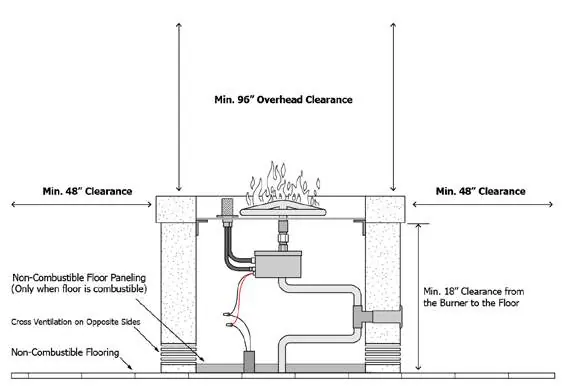
- Clearances: Maintain a minimum of 48 inches from sides to structures or combustibles and 96 inches of overhead clearance.
- Flooring: Must be installed on non-combustible flooring. If installed on a combustible surface (e.g., wood deck), non-combustible floor paneling must be installed underneath.
Mounting and Gas Connections
The gas piping should be installed underground between fire bowls and reduced to 1/2" NPT at each bowl. Use only stainless steel whistle-free hoses; do not use yellow corrugated flex lines. Secure the mounting bracket to the location using anchors rated for the material. The center cutout hole must be no larger than 4 inches square or diameter to ensure the bracket is properly secured.
Electronic Ignition System Installation
Follow these steps to install the electronic ignition system:
- Ensure the gas riser is centered in the bowl.
- Apply pipe dope or plumber's tape to the gas stub and thread the valve box onto the riser. Ensure the valve is upright.
- Perform a gas leak test on the valve connections using a soapy water solution.
- Connect the black and red wires from the valve box to the low voltage wires from the electrical conduit using wire nuts.
- Connect the Pilot Burner Assembly to the Electronic Valve using the white quick-connect for electricity and the brass fitting for gas. Ensure you hear a "click" when connecting the electrical plug.
Media Installation
Use only approved media such as fire-rated lava rock, fire glass, or man-made stone. Do not use non-porous materials like river rocks, as they can trap moisture and fracture when heated. The media layer should be 2" to 3" thick. Important: Do not cover the top of the pilot burner, as this will cut off air required for ignition and cause the system to overheat.
Operation and Maintenance
To start the fire feature, turn on the electrical device powering the system. The hot surface igniter will heat up, followed by the pilot gas valve opening. The pilot flame should be visible within 10 seconds, followed by the main burner ignition. To shut down, turn off the electrical power. Perform semi-annual inspections for debris or insect infestation in the pilot burner and burner holes. Clean as necessary using compressed air.
Troubleshooting
If the system fails to ignite, check for air in the gas line (cycle the power several times to purge) or insufficient electrical current. If the glow plug is not getting hot enough, verify that you are using at least 12-gauge wire. If small flames persist after shutdown, cycle the power to dislodge debris from the valve.
Practical help
Common problems
System turned on but nothing happens
Check all electrical connections at the transformer and fire feature. Use a multimeter to confirm a minimum of 12 volts at the fire feature.
Glow plug glows but no ignition
Purge air from the gas line by cycling the power. If that fails, check for insufficient electrical current (amps) due to incorrect wire gauge.
Small flames remain after shutdown
Debris may be caught in the valve. Cycle the power several times to dislodge debris. If it persists, turn off the manual gas shutoff.
Before use
- Verify gas type (Natural Gas or Propane) and supply pressure.
- Ensure 12VAC power supply is used (do not use 110V).
- Test all gas connections for leaks using a leak detector or soapy water.
- Confirm minimum clearances (48" sides, 96" overhead) are met.
- Inspect the fire feature for debris (leaves, etc.) before starting.
- Ensure media is installed correctly and does not cover the pilot.
Images and diagrams
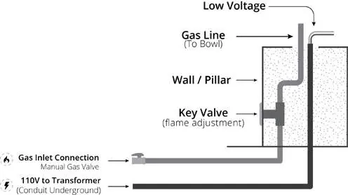
- Wiring Diagram: Shows the connection from 110V power to the 12V transformer and the fire bowl.
- Clearance Diagram: Illustrates the required distances from combustibles and floor requirements.
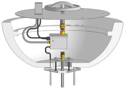
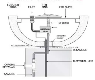
- Component Overview: Identifies the burner ring, pilot igniter, and valve assembly.
Model compatibility
- Requires 12VAC power only; 110V will damage the system.
- Use only stainless steel whistle-free hoses; do not use yellow corrugated lines.
- Must be installed on non-combustible flooring or use non-combustible floor paneling.

Manual page author
Emily Carter
User documentation editor
Prepares concise manual descriptions and highlights the most useful setup, operation, and maintenance information for readers.