Garden / Fire Pits
User Manual for The Outdoor Plus Smart Weather Electronic Ignition System (SWEIS)
Quick guide for The Outdoor Plus Smart Weather Electronic Ignition System (SWEIS). Includes installation steps, wiring diagrams, operation, maintenance, and troubleshooting.
Table of contents
Manual images
Click an image to enlargeQuick Guide from the Manual
The Smart Weather Electronic Ignition System (SWEIS) is designed for outdoor fire features. Installation must be performed by a qualified installer. Key requirements include proper ventilation (1 square inch per 25,000 BTUs), correct gas pressure, and adherence to local codes. The unit is water-resistant but not waterproof; do not submerge.
System Overview
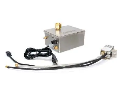
The SWEIS utilizes CSA-certified components, including a Hot Surface Igniter (HSI), TC Flame-sense system, and LED diagnostics. It operates on 110V AC power. The system is designed to withstand outdoor conditions with a temperature range of -20° to 175° F.
Installation
Gas Connection: Ensure the appliance is compatible with the gas type. A manual gas shutoff device must be installed prior to the appliance. Use thread sealant on all pipe connections. A heat shield must be installed between the SWEIS and the burner ring to prevent overheating.
Pilot Assembly: Mount the pilot on top of the burner pan. The pilot is configured for natural gas; a propane injector is provided if needed. Keep the pilot within 1 inch of a burner port. Perform a leak test using a noncorrosive leak check solution after installation.
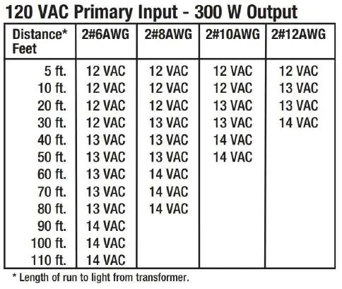
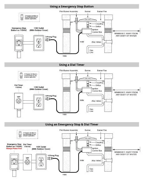
Electrical: The system requires 110V AC power. Use 12 gauge wire for runs up to 50 feet and 10 gauge for runs over 50 feet. Use dielectric grease on all wire nuts.
Operation
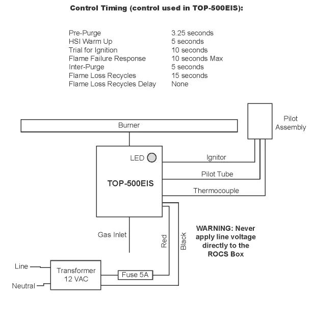
Start-up: Visually inspect the fire feature for debris before turning it on. Turn on the electrical device to power the system. The unit will perform a pre-purge, HSI warm-up, and trial for ignition. If the flame is detected, the main valve opens.
Shutdown: Turn off the electrical device used to power the fire feature.
Maintenance
Prior to each use: Inspect for debris and remove it.
Semi-annually: Visually inspect the pilot igniter for debris or insect infestation (spider webs) and clean burner holes. Use compressed air if necessary.
Annually: Inspect the pilot igniter for excess corrosion and test the fire feature for proper operation.
Troubleshooting
The system features LED diagnostics to assist in troubleshooting:
- 1 Flash: Hot start, thermocouple hot at power up.
- 2 Flashes: Trial lockout, maximum ignition trials exceeded.
- 3 Flashes: Flame loss lockout.
- 4 Flashes: Flame sense fault.
- 5 Flashes: Valve fault.
- Fast Flash: Safety shutdown.
If the system does not ignite, check for air in the gas line (purge if necessary) or low electrical current (check wire gauge and transformer voltage).
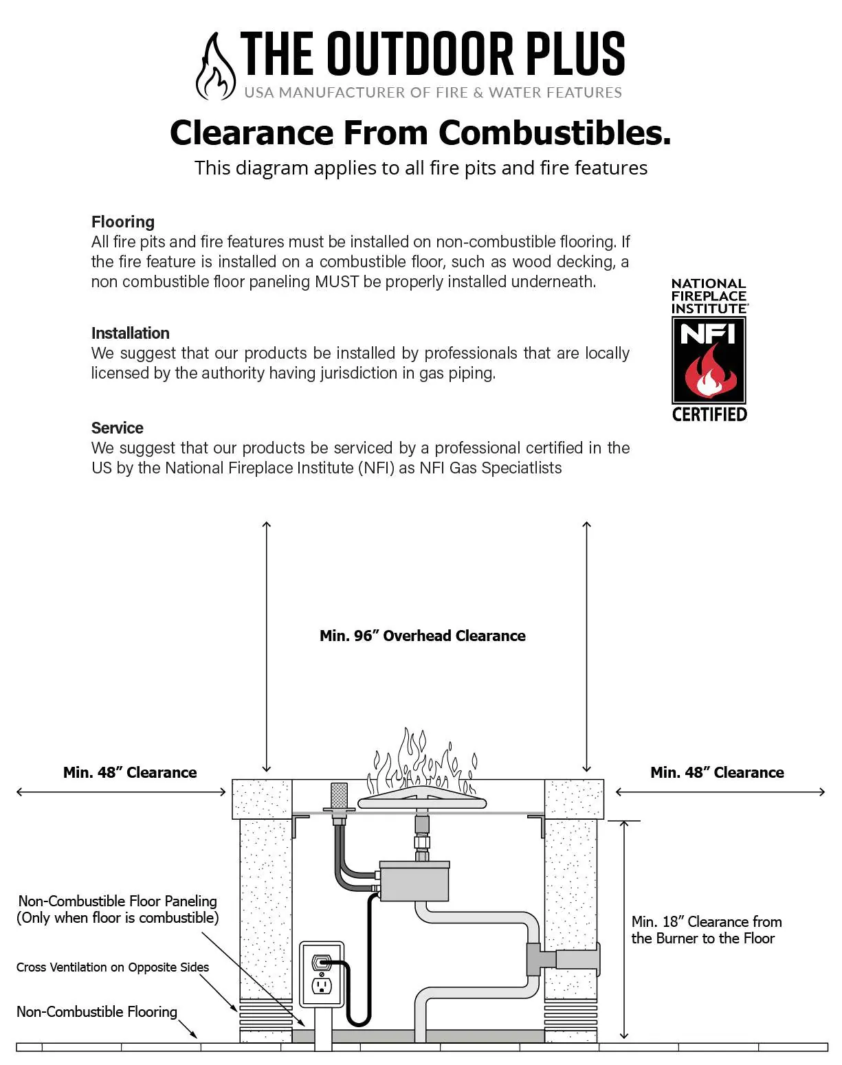
Clearance from Combustibles
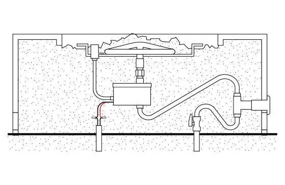
All fire pits must be installed on non-combustible flooring. If installed on a combustible floor, non-combustible floor paneling must be installed underneath. Maintain minimum clearances as specified in the installation diagrams.
Practical help
Common problems
Nothing happens when turned on
Check electrical connections, ensure transformer is producing at least 12V, and verify wire gauge is sufficient.
Igniter glows but no ignition
Purge air from the gas line, check gas pressure, or verify amperage (should be 1.4-1.6A initially, jumping to 2.0A).
Small flames flickering after shutdown
Debris in the gas line may be preventing the valve from closing. Cycle the power on and off to dislodge debris.
Before use
- Inspect fire feature for debris
- Ensure gas shut-off valve is open
- Verify adequate cross-ventilation
- Check for gas leaks using noncorrosive solution
- Ensure media does not cover the pilot assembly
Specs in practice
- 12 gauge wire
- Required for electrical runs up to 50 feet.
- 10 gauge wire
- Required for electrical runs over 50 feet.
- 1 square inch
- Minimum ventilation required per 25,000 BTUs.
Images and diagrams
- Wiring diagrams for emergency stop and dial timer configurations
- Pilot assembly installation and connection
- Clearance requirements from combustible materials
Model compatibility
- For outdoor use only
- Not waterproof; do not submerge
- Requires 110V AC power

Manual page author
Michael Turner
Technical manual editor
Reviews PDF manuals for structure, safety notes, and practical product details so readers can find the right information quickly.