Tools / Magnifying Lamps
Operating Instructions for Toolcraft Compressed Air Hose Reel
Quick guide for the Toolcraft compressed air hose reel. Includes installation, operation, spring force adjustment, maintenance, and troubleshooting steps.
Table of contents
Quick Guide
This manual provides instructions for the Toolcraft compressed air hose reel. The device is designed for indoor use with compressed air. Important: Always disconnect the air supply before performing any maintenance or adjustments. Do not use in explosive environments or outdoors.
Operating Elements
The hose reel consists of the following main components:
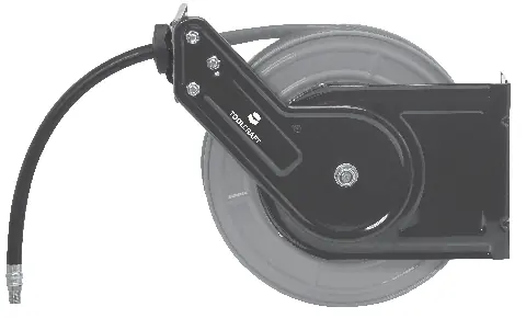
- 1: Coupling piece (1/4")
- 2: Base plate
- 3: Hose stop unit
- 4: Guide rollers
- 5: Hose stop ring
- 6: Hose drum
- 7: Coupling (1/4")
- 8: Supply hose
- 9: Guide arm
Installation
The hose reel can be mounted on walls, columns, floors, or ceilings.
- Determine a suitable location near a compressed air source with a 1/4" connection.
- Use the included drill template to mark the four mounting holes.
- Drill holes according to the surface type (carbide bits for mineral surfaces, metal bits for wood/metal).
- Use appropriate screws and dowels (not included) to secure the base plate. Ensure washers are used to spread the force.
- Connect the compressed air inlet to your air supply. It is recommended to install a shut-off valve for maintenance.
Operation
Unrolling the hose
Pull the hose to the desired length. Allow it to retract slightly until it clicks into place. Do not pull beyond the full length of the hose to avoid damage or injury.
Rolling the hose
Pull the hose slightly to release the locking mechanism. Guide the hose slowly and steadily back onto the drum. Warning: Never let go of the hose while it is retracting, as it may whip back and cause injury or damage.
Settings
Adjusting hose length
Loosen the two screws on the hose stop ring (5), slide it to the desired position, and retighten the screws.
Adjusting the guide arm
The guide arm (9) can be adjusted in 90° increments. Loosen the hexagonal nut on the base plate, rotate the arm to the desired position, and retighten the nut.
Adjusting spring force
Caution: Always hold the hose drum (6) firmly when adjusting spring force.
- Remove the hose stop ring (5).
- Pull the hose end over the guide rollers.
- Rotate the drum anticlockwise (from the inlet side) to decrease force, or clockwise to increase force.
- Reinstall the hose stop ring after adjustment.
Maintenance
The unit is low-maintenance. Keep the hose clean and free of dirt. Regularly check valves, connections, and mounting hardware for leaks, cracks, or looseness. Repairs should only be performed by a specialist.
Troubleshooting
If the hose does not wind back fully, ensure it is rolled evenly and slowly, or check if the spring tension is too low. If the hose does not click into place, check the installation or the locking mechanism. If air escapes, check for hose damage, worn seals, or loose clamps.
Practical help
Common problems
Hose does not wind back fully
Roll the hose slowly and evenly. Check if the spring tension is too low or if the replacement hose is too heavy.
Hose does not click into place
Ensure the reel is installed correctly. Guide the hose slowly back onto the drum.
Air leaks
Check for hose damage, worn seals on the drum, or loose hose clamps.
Before use
- Check for visible damage to the hose or housing
- Ensure the mounting surface is stable and load-bearing
- Install a shut-off valve in the air supply line
- Wear appropriate protective equipment (goggles, ear protection)
Specs in practice
- Working pressure
- 10 bar
- Minimum bursting pressure
- 40 bar
Images and diagrams
- 1: Coupling piece (1/4")
- 2: Base plate
- 3: Hose stop unit
- 4: Guide rollers
- 5: Hose stop ring
Model compatibility
- Indoor use only
- Not for use in explosive environments
- Compatible with 1/4" compressed air connections

Manual page author
Michael Turner
Technical manual editor
Reviews PDF manuals for structure, safety notes, and practical product details so readers can find the right information quickly.