Industrial / Gasoline Engines
User Manual for Topmaq 1300W Mini Polisher
Quick guide for the Topmaq 1300W Mini Polisher. Includes assembly instructions, speed adjustment, operation tips, maintenance, and parts diagram.
Table of contents
Manual images
Click an image to enlargeQuick Guide
This manual provides essential safety and operational instructions for the Topmaq 1300W Mini Polisher. Always ensure the machine is unplugged before performing any adjustments, maintenance, or changing accessories. The machine features dual power control: an ON-OFF switch and a speed controller. Ensure both are in the OFF position before connecting to power.
Specifications
- Rated input power: 1300W
- No load speed: 500-8000 RPM
- Chuck capacity: 1-10mm
- Fiber wheel size: 75x10x20mm
- Shaft chuck capacity: 0.3-4mm
Assembly
Before assembly, compare the contents of the shipping container with the manual list. Clean rust-protected surfaces with kerosene or a light solvent; do not use lacquer thinner or gasoline as they damage plastic components.
Mounting Attachments:
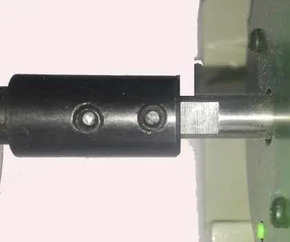
- Ensure the two set screws on the spindle are released before assembly.
- Slide the spindles or mandrels onto the motor shaft as deep as possible, ensuring the set screws line up with the flat on the motor shaft.
- Tighten both screws securely using a 2.5mm Hex Key.
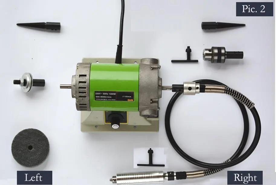
- Note: Some parts are side-specific. The fiber wheel must be mounted on the left. The flexible shaft and drill chuck must be mounted on the right. Taper spindles marked with 'L' go on the left, and 'R' go on the right.
Adjustment
The machine features electronic variable speed control. To adjust the speed, rotate the adjustment knob. Clockwise rotation increases speed, while counter-clockwise rotation decreases it.
Switching Off: The machine has two 'OFF' points: the main ON-OFF switch and the OFF position on the speed controller. Rotate the adjustment knob counter-clockwise until you hear a ticking sound to turn off the speed controller, and press the 'O' side of the main switch to ensure the machine is fully powered off.
Operation
Do not allow the tool to contact the workpiece surface when turning the tool on or off to prevent poor finishing or belt damage. Different buffing wheels can be used to achieve various surface speeds. Generally, lower surface speeds are recommended for polishing, while higher speeds are better for buffing.
Maintenance
Service: All service should be performed by a Factory Authorized Service Station to avoid misplacing internal wires or components.
Tool Lubrication: Gears should be regreased with a special gear lubricant at every brush change.
Carbon Brushes: Examine the brushes every 50 hours of operation to maintain peak motor efficiency. Use only genuine replacement brushes.
Cleaning: Disconnect from power before cleaning. Use compressed dry air to clean the machine. Avoid using gasoline, carbon tetrachloride, or ammonia-based detergents, as these damage plastic parts.
Parts Diagram
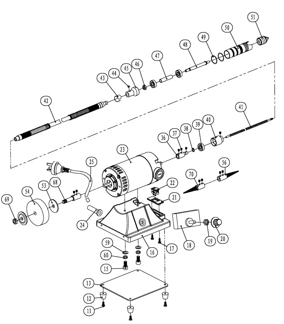
Refer to the exploded view diagram for identification of all components, including the motor, speed controller, flexible shaft, and various spindles.
Practical help
Common problems
Machine will not start
Ensure the main ON-OFF switch is in the ON position and the speed controller knob is turned up from the 'OFF' position.
Attachment releases during operation
Verify that the correct spindle/mandrel is mounted on the correct side (Left/Right) and that the set screws are tightened securely with a 2.5mm Hex Key.
Poor sanding or polishing finish
Ensure the tool is not in contact with the workpiece when turning the machine on or off.
Before use
- Check that the outlet voltage matches the machine nameplate.
- Ensure the switch is in the OFF position before plugging in.
- Verify all safety guards are in place.
- Ensure the workpiece is securely clamped to a stable platform.
- Check that the correct spindle/mandrel is mounted on the correct side.
Specs in practice
- Rated input power
- 1300W - The power consumption of the motor.
- No load speed
- 500-8000 RPM - The adjustable speed range of the spindle.
- Chuck capacity
- 1-10mm - The size range of drill bits or accessories the chuck can hold.
Images and diagrams
- The parts diagram identifies all components, including the motor (23), speed controller (18), and various spindles (56, 70).
Model compatibility
- Fiber wheel must be mounted on the left side.
- Flexible shaft and drill chuck must be mounted on the right side.
- Taper spindles marked 'L' are for the left, 'R' for the right.

Manual page author
David Miller
Documentation analyst
Organizes user manual content into clear summaries, with attention to model details, product context, and everyday usability.