General / Other Manuals
Fuel Pump System Service Manual for Toyota
Comprehensive guide for Toyota fuel pump system inspection, pressure testing, removal, and installation, including technical specifications and torque settings.
Table of contents
Quick guide from the manual
This document provides technical procedures for the inspection and maintenance of the Toyota fuel pump system. It covers on-vehicle fuel pump operation checks, fuel pressure testing, and the complete removal and installation process for the fuel pump assembly.
On-vehicle inspection
To check fuel pump operation:
- Turn the ignition switch to ON (do not start the engine).
- Use the Special Service Tool (SST 09843-18020) to connect terminals FP and +B of the DLC1 connector.
- Verify pressure in the fuel inlet hose; you should hear fuel return noise from the return hose.
If no pressure is detected, inspect the fusible link, EFI 15A fuse, IGN 7.5A fuse, EFI main relay, circuit opening relay, the fuel pump itself, and all wiring connections.
Fuel pressure testing
Before testing, ensure the battery voltage is above 12V and disconnect the negative terminal. Use a pressure gauge (SST 09268-45012) connected to the LH delivery pipe with new gaskets, torqued to 34 N-m (350 kgf-cm, 25 ft-lbf).
- Standard pressure: 265–304 kPa (38–44 psi).
- Pressure at idling (vacuum hose disconnected): 265–304 kPa (38–44 psi).
- Pressure at idling (vacuum hose connected): 226–255 kPa (33–37 psi).
- Residual pressure: Must remain above 147 kPa (21 psi) for 5 minutes after engine shutdown.
Fuel pump removal and installation
Caution: Do not smoke or work near open flames when handling fuel components.
Removal steps:
- Drain fuel from the fuel tank.
- Remove the fuel tank.
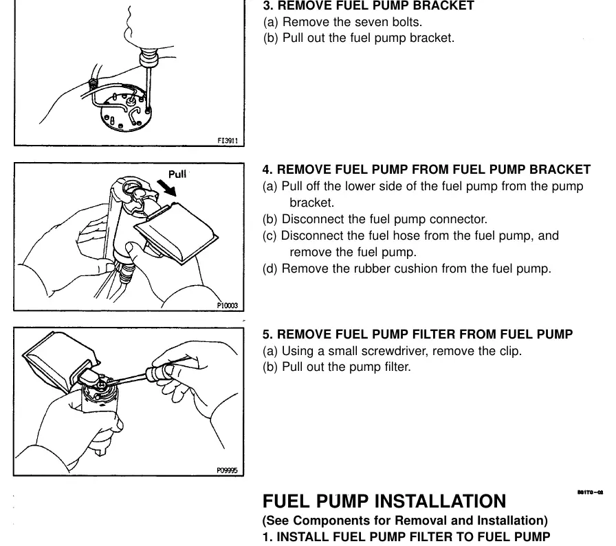
- Remove the seven bolts securing the fuel pump bracket and pull it out.
- Disconnect the fuel pump connector and hose, then remove the pump from the bracket.
- Remove the rubber cushion and the fuel pump filter (using a small screwdriver to remove the clip).
Installation steps:
- Install the new filter with a new clip.
- Attach the rubber cushion and connect the fuel hose and connector.
- Push the pump into the bracket.
- Install the bracket onto the fuel tank with a new gasket and tighten the seven bolts to 3.9 N-m (40 kgf-cm, 34 in-lbf).
- Ensure all hoses are properly secured with clips and tightened to specified torque.
Practical help
Common problems
No fuel pressure during inspection
Check fusible link, EFI 15A/IGN 7.5A fuses, EFI main relay, circuit opening relay, fuel pump, and wiring.
High fuel pressure
Replace the fuel pressure regulator.
Low fuel pressure
Check fuel hoses/connections, fuel pump, fuel filter, and fuel pressure regulator.
Pressure drops rapidly after engine shutdown
Check fuel pump, fuel pressure regulator, and/or injectors.
Before use
- Ensure battery voltage is above 12V
- Have SST 09843-18020 available for electrical testing
- Have SST 09268-45012 available for pressure testing
- Prepare new gaskets for fuel pipe connections
- Ensure a fire-safe environment (no smoking/open flames)
Specs in practice
- Standard Fuel Pressure
- 265–304 kPa (38–44 psi) during operation.
- Residual Pressure
- Must stay above 147 kPa (21 psi) for 5 minutes after engine stop.
- Delivery Pipe Bolt Torque
- 34 N-m (350 kgf-cm, 25 ft-lbf).
- Fuel Pump Bracket Bolt Torque
- 3.9 N-m (40 kgf-cm, 34 in-lbf).
Images and diagrams
- Circuit diagram shows the relationship between the EFI main relay, circuit opening relay, and fuel pump.
- SST connection points (FP and +B) are located in the DLC1 connector.
- Exploded view shows the assembly order of the fuel pump, filter, and rubber cushion.
Model compatibility
- Procedures apply to MFI (Multiport Fuel Injection) systems.
- Always use new gaskets when reconnecting fuel pipes to prevent leaks.

Manual page author
Michael Turner
Technical manual editor
Reviews PDF manuals for structure, safety notes, and practical product details so readers can find the right information quickly.