Tools / Lifting Tools
User Manual for Vevor Floor Support Jacks
A comprehensive user guide for Vevor Floor Support Jacks. Includes safety instructions, step-by-step usage procedures for various models, maintenance tips, and technical specifications.
Quick answers from the manual
Quick answer
- The Vevor Floor Support Jacks are designed for structural support. Always place them on flat, stable surfaces and never exceed the calibrated load capacity. p. 2, 3
Key actions
- Place the support rod vertically on a flat surface. p. 3, 4, 5, 6
First start
- Inspect the jack for any damage before use. p. 6
Maintenance and reset
- Wipe the surface clean, remove rust if present, and apply lubricating and rust-proof grease. p. 6
Technical specifications
| Parameter | Value | Meaning | Pages |
|---|---|---|---|
| Max loading | 2500lbs - 24700lbs | Varies by model | p. 5, 6 |
Where to find it in the PDF
- Safety Instructions p. 2
- Usage Steps p. 3, 4, 5
- Model List p. 5, 6
- Maintenance p. 6
Table of contents
Manual images
Click an image to enlargeQuick guide from the manual
This document provides instructions for the safe operation and maintenance of Vevor Floor Support Jacks. Users must ensure the jack is placed on a flat, stable surface and that the load does not exceed the calibrated capacity for the specific model.
Safety instructions and precautions
- Prohibited surfaces: It is strictly prohibited to place support rods on uneven or sloping roads and platforms.
- Load capacity: Always use the jack according to its calibrated load capacity. Overloading is strictly prohibited.
- Personal safety: Strictly observe the placement during use and pay attention to personal safety.
- Model selection: Choose a suitable jack model to ensure it meets the required load-bearing capacity and height requirements.
Operating instructions
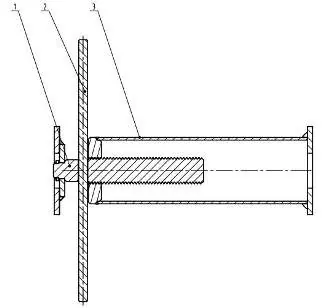
Model 204A-0040-00-00
- Place the support rod vertically on a flat surface.
- Rotate component 1 (Height adjusting assembly) to the desired height.
- Clockwise lock the hexagonal nut onto the plane of support seat 3.
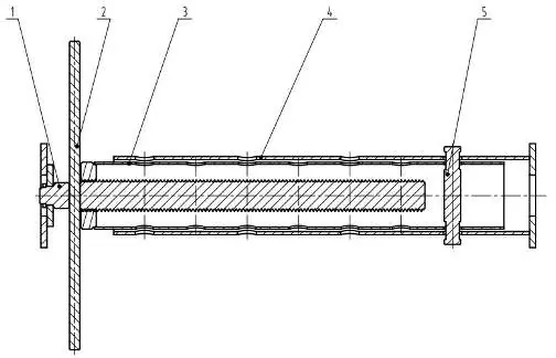
Model 204A-0080-00-00 / 204A-0080-01-00 / 204A-0080-02-00
- Place the support rod vertically on a flat surface.
- Insert component 1 (Inner cylinder support group) into component 4 (Support seat).
- Adjust to the required height and insert safety pin 5 to fix it.
- Use the Handle Rocker to screw out the Height adjusting assembly 1 clockwise to the desired position.
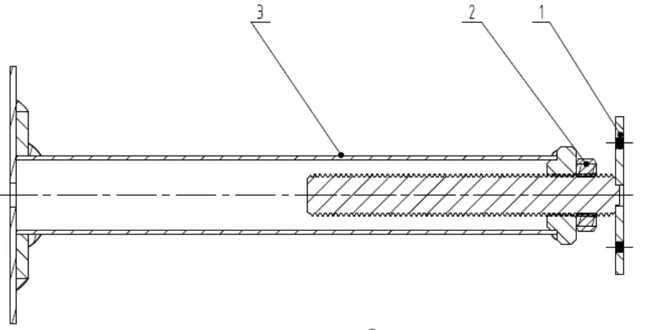
Model 204A-0045-00-00 / 204A-0045-01-00 / 204A-0110-00-00
- Place the support rod vertically on a flat surface.
- Use component 2 (Handle rocker) to adjust component 1 (Height adjustment).
- Tighten component 3 (Support seat) to prevent shaking.
- Rotate the assembly to the desired height.
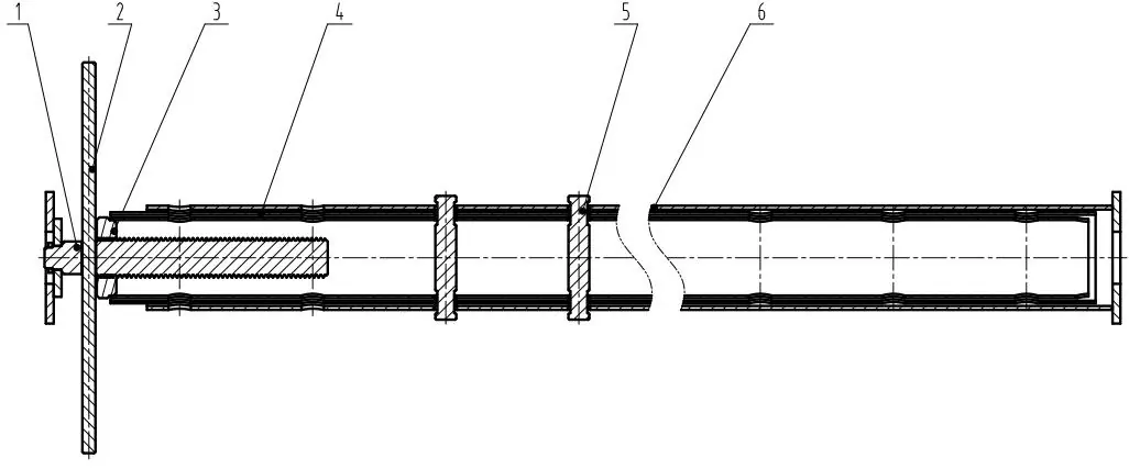
Model 204A-0050-00-00
- Place the support rod vertically on a flat surface.
- Insert component 4 (Outer cylinder support seat) into component 6 (Support seat), adjust height, and insert component 5 (Safety pin) to fix.
- Insert component 3 (Inner cylinder support group) into component 4, adjust height, and insert component 5 (Safety pin) to fix.
- Use component 2 (Handle Rocker) to screw out component 1 (Height adjusting assembly) clockwise to the desired position.
Model specifications
The following models are available with varying load capacities and adjustable heights:
- 204A-0040-00-00: 2500lbs capacity, 12-16 inches adjustable.
- 204A-0045-00-00 / 204A-0045-01-00: 9700lbs capacity, 12-16 inches adjustable.
- 204A-0080-00-00: 18000lbs capacity, 19-36 inches adjustable.
- 204A-0080-01-00: 18000lbs capacity, 53-93 inches adjustable.
- 204A-0050-00-00: 11200lbs capacity, 54-150 inches adjustable.
- 204A-0080-02-00: 18000lbs capacity, 56-100 inches adjustable.
- 204A-0110-00-00: 24700lbs capacity, 13.2-18.7 inches adjustable.
Maintenance and upkeep
- Inspection: After use, carefully inspect components for damage and test performance. Repair any abnormalities immediately.
- Cleaning: Wipe the surface clean to prevent debris from causing corrosion. Remove rust spots if they appear.
- Lubrication: Apply lubricating grease and rust-proof grease to the jack.
- Storage: Store in a dry and ventilated place.
Manufacturer information
VEVOR
Practical help
Common problems
Rust spots on surface
Remove rust promptly to avoid damage to the jack.
Components damaged
Perform inspection after use and repair abnormalities immediately.
Before use
- Ensure the surface is flat and stable.
- Verify the load capacity is sufficient for the application.
- Inspect all components for damage before use.
Specs in practice
- Adjustable size
- The height range the jack can be set to.
Images and diagrams
- Components are numbered in diagrams to assist with assembly and identification.
- Handle rockers are used for height adjustment on specific models.
Model compatibility
- Do not use on uneven or sloping surfaces.
- Ensure the chosen model meets load-bearing and height requirements.

Manual page author
Emily Carter
User documentation editor
Prepares concise manual descriptions and highlights the most useful setup, operation, and maintenance information for readers.